Understanding your vehicle’s engine speed is crucial for diagnostics and performance monitoring. The On-Board Diagnostics II (OBD2) system provides access to this data, and with an MCP2515 CAN controller and Arduino, you can easily retrieve it. This guide will walk you through how to request engine speed (PID 0C) using the MCP2515 and interpret the data received.
Setting Up Your MCP2515 with Arduino for OBD2 Communication
To begin, you’ll need an MCP2515 CAN bus module connected to your Arduino. This module acts as an interface, allowing your Arduino to communicate with your vehicle’s CAN bus network, where OBD2 data is transmitted. The following Arduino code provides a foundation for sending and receiving CAN messages, specifically tailored for OBD2 PID requests.
#include <mcp_can.h>
#include <SPI.h>
// CAN Interrupt and Chip Select Pins
#define CAN0_INT 2
MCP_CAN CAN0(10); // CS pin for MCP2515
// Define CAN IDs - Extended IDs are used here
#define LISTEN_ID 0x98DAF101
#define REPLY_ID 0x98DA01F1
#define FUNCTIONAL_ID 0x98DB33F1
// CAN TX Variables
unsigned long prevTx = 0;
unsigned int invlTx = 1000; // Transmit interval: 1 second
byte txData[] = {0x02, 0x01, 0x0C, 0x55, 0x55, 0x55, 0x55, 0x55}; // Request PID 0C (Engine Speed)
// CAN RX Variables
unsigned long rxID;
byte dlc;
byte rxBuf[8];
char msgString[128];
void setup() {
Serial.begin(115200);
while (!Serial);
// Initialize MCP2515
if (CAN0.begin(MCP_STDEXT, CAN_500KBPS, MCP_8MHZ) == CAN_OK) {
Serial.println("MCP2515 Initialized Successfully!");
} else {
Serial.println("Error Initializing MCP2515... Check connections!");
while (1);
}
// Extended ID Filters - Adjust masks and filters as needed for your application
CAN0.init_Mask(0, 0x90FF0000);
CAN0.init_Filt(0, 0x90DA0000);
CAN0.init_Filt(1, 0x90DB0000);
CAN0.init_Mask(1, 0x90FF0000);
CAN0.init_Filt(2, 0x90DA0000);
CAN0.init_Filt(3, 0x90DB0000);
CAN0.init_Filt(4, 0x90DA0000);
CAN0.init_Filt(5, 0x90DB0000);
CAN0.setMode(MCP_NORMAL);
pinMode(CAN0_INT, INPUT);
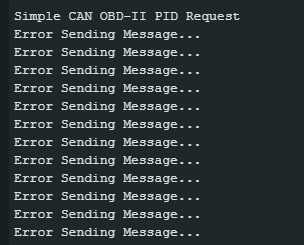
Serial.println("Simple CAN OBD-II PID Request");
}
void loop() {
// Check for incoming CAN messages
if (!digitalRead(CAN0_INT)) {
CAN0.readMsgBuf(&rxID, &dlc, rxBuf);
// Display received CAN data
if ((rxID & 0x80000000) == 0x80000000) {
sprintf(msgString, "Extended ID: 0x%.8lX DLC: %1d Data:", (rxID & 0x1FFFFFFF), dlc);
} else {
sprintf(msgString, "Standard ID: 0x%.3lX DLC: %1d Data:", rxID, dlc);
}
Serial.print(msgString);
if ((rxID & 0x40000000) == 0x40000000) {
sprintf(msgString, " REMOTE REQUEST FRAME");
Serial.print(msgString);
} else {
for (byte i = 0; i < dlc; i++) {
sprintf(msgString, " 0x%.2X", rxBuf[i]);
Serial.print(msgString);
}
}
Serial.println();
}
// Send PID 0C request every second
if ((millis() - prevTx) >= invlTx) {
prevTx = millis();
if (CAN0.sendMsgBuf(FUNCTIONAL_ID, 8, txData) == CAN_OK) {
Serial.println("Message Sent Successfully!");
} else {
Serial.println("Error Sending Message...");
}
}
}This code initializes the MCP2515, sets up filters to receive relevant CAN messages, and sends a request for PID 0C every second. Let’s break down the key parts and how to interpret the results.
Understanding the Code for PID 0C Request
-
#include <mcp_can.h>and#include <SPI.h>: These lines include necessary libraries for MCP2515 CAN communication and SPI communication, which the MCP2515 uses. -
MCP_CAN CAN0(10);: This line initializes the MCP_CAN object, specifying pin 10 as the Chip Select (CS) pin for the MCP2515. Note: Older shields might use pin 9. -
byte txData[] = {0x02, 0x01, 0x0C, 0x55, 0x55, 0x55, 0x55, 0x55};: This is the crucial line for requesting PID 0C. Let’s dissect it:0x02: Specifies the number of bytes following in the request (Service ID + PID).0x01: This is the Service ID for “Show current data” in OBD2.0x0C: This is the PID code for “Engine speed”.0x55, 0x55, 0x55, 0x55, 0x55: These are padding bytes and are generally ignored by the ECU.
-
FUNCTIONAL_ID:0x98DB33F1(Extended ID) or0x7DF(Standard ID – commented out in this example) is the functional request ID used to broadcast the OBD2 request to all ECUs on the CAN bus. The ECU responsible for engine data will respond. -
CAN0.sendMsgBuf(FUNCTIONAL_ID, 8, txData): This function sends the CAN message with theFUNCTIONAL_ID, data length of 8 bytes, and thetxData(our PID 0C request).
Interpreting the Received Data for Engine Speed
When you run this code and open your Arduino Serial Monitor, you should see CAN messages being received. To find the engine speed, look for messages where the data corresponds to a response to your PID 0C request. OBD2 responses usually follow a specific format.
If your request is successful, you should receive a CAN message back. The data bytes in the response for PID 0C (Engine Speed) are typically formatted as follows:
- Byte 1: Number of bytes in the response (excluding this byte itself).
- Byte 2:
0x41– Positive response Service ID (0x40 + Service ID requested, which was 0x01). - Byte 3:
0x0C– The PID you requested (Engine Speed). - Byte 4 (MSB): Most Significant Byte of the Engine Speed value.
- Byte 5 (LSB): Least Significant Byte of the Engine Speed value.
Calculating Engine Speed (RPM):
The engine speed is calculated from byte 4 and byte 5 using the following formula:
Engine Speed (RPM) = ((Byte 4 * 256) + Byte 5) / 4
For example, if you receive the following data bytes in response to your PID 0C request: 0x03 0x41 0x0C 0x0B 0xB8
- Byte 4 =
0x0B= 11 (decimal) - Byte 5 =
0xB8= 184 (decimal)
Engine Speed (RPM) = ((11 * 256) + 184) / 4 = (2816 + 184) / 4 = 3000 / 4 = 750 RPM
This indicates an engine speed of 750 RPM, which is a typical idle speed.
Troubleshooting and Verifying Your Setup
If you are not seeing the expected engine speed values or are encountering issues, consider the following:
- Wiring: Double-check your MCP2515 module wiring to the Arduino and the OBD2 port. Ensure proper CAN High and CAN Low connections.
- Baud Rate: Verify that the CAN baud rate (
CAN_500KBPSin the code) matches your vehicle’s OBD2 CAN bus speed. 500kbps is the most common for OBD2. - Vehicle Compatibility: Ensure your vehicle supports OBD2 CAN communication and PID 0C. Most modern vehicles (post-1996 in the US, post-2001/2004 in Europe/Asia) should support OBD2.
- Filters and Masks: The CAN filters and masks in the code are set for extended IDs. If you are using standard IDs, you may need to adjust these or disable filtering initially for testing to see all CAN traffic and identify the correct response IDs.
- Engine State: Make sure your vehicle’s engine is running when you are requesting engine speed, as the ECU will only provide live data when the engine is active.
If you are still having trouble, examine the raw CAN data you are receiving in the Serial Monitor. Look for patterns and CAN IDs that might be related to engine data. Consulting your vehicle’s service manual or online OBD2 PID resources might also be helpful in identifying the correct PIDs and expected responses for your specific vehicle.
 MCP2515 Module connected to Arduino for CAN Bus communication
By following this guide and carefully reviewing your setup, you should be able to successfully request and decode engine speed data from your vehicle’s OBD2 system using the MCP2515 and Arduino. This is just the beginning – the OBD2 standard offers a wealth of diagnostic and performance data that you can access and utilize for your automotive projects.