Creating your own OBD2 USB cable can be a rewarding project for car enthusiasts and DIYers. This guide provides a step-by-step approach to building your own cable, allowing you to connect your car’s On-Board Diagnostics II (OBD2) system to a USB interface for diagnostics and data monitoring. Please be aware that this is a DIY project and should be undertaken at your own risk. We are not responsible for any damage that may occur to your vehicle or equipment.
Tools and Parts You’ll Need
Before you begin, gather the necessary tools and parts. This will ensure a smooth and efficient building process.
Tools:
- Wire strippers/cutters: Essential for preparing the wires for connection.
- Needle-nose pliers: Helpful for manipulating small components and wires.
- Molex crimping tool (Optional but Recommended): While not strictly necessary, a crimping tool ensures secure and professional connections.
- Soldering iron (Recommended): Soldering provides a robust and reliable connection, especially for delicate wires.
Parts:
- 4-Pin Connector: This connector will interface with your diagnostic device. Ensure it is compatible with your intended use. (4-pin connector example; pin/wire size = 22-16AWG; insulation/seal size = 1.3-1.7mm)
- OBD-II Cable: This cable has the OBD2 connector to plug into your vehicle. (OBD-II Cable example)
If you prefer to customize your cable further and have spare wire available, you can purchase just the female OBD-II connector and use your own wires to connect the OBD-II and 4-pin connectors. Ensure you select a 4-pin connector compatible with your wire gauge.
Understanding OBD2 Wiring
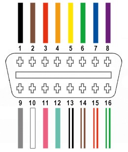
The OBD2 connector has 16 pins, but for our USB cable, we only need to focus on four key wires. These wires are crucial for CAN bus communication, the standard protocol for vehicle diagnostics in most modern cars.
The four essential pins on the OBD2 connector are:
- Pin 4 (Chassis Ground): Provides the ground connection for the circuit. (Orange wire in the example OBD2 cable)
- Pin 6 (CAN [J-2234] High): Carries the CAN High signal for data communication. (Green wire in the example OBD2 cable)
- Pin 14 (CAN [J-2234] Low): Carries the CAN Low signal for data communication. (Brown with white stripe wire in the example OBD2 cable)
- Pin 16 (Battery Power): Supplies power to the OBD2 device. (Green with white stripe wire in the example OBD2 cable)
Step-by-Step Guide to Making Your OBD2 USB Cable
Let’s walk through the process of building your OBD2 USB cable.
Step 1: Prepare the OBD2 Cable Wires
Start by preparing the OBD2 cable. Carefully remove the outer sheath and shielding from the end of the OBD2 cable to expose the individual wires inside. Identify the four wires you need – Chassis Ground (Pin 4), CAN High (Pin 6), CAN Low (Pin 14), and Battery Power (Pin 16) – based on their colors as listed above (orange, green, brown/white, green/white in our example cable). Separate these four wires from the rest and use a zip tie or similar to bundle the unused wires and keep them out of the way.
Step 2: Prepare the Wires for the 4-Pin Connector
The wires in the example OBD2 cable are 26AWG, which is slightly smaller than the 22AWG size recommended for the pins of the 4-pin connector. To ensure a secure connection, we need to “thicken” the wire ends.
Carefully strip about 3/8″ of insulation from the end of each of the four selected wires. Fold the exposed wire strands back over themselves and twist them tightly. This effectively doubles the wire thickness, making it a better fit for the 4-pin connector pins. Slide a rubber seal (from the 4-pin connector kit) onto each wire.
Step 3: Attach Wires to 4-Pin Connector Pins
Take one pin from the 4-pin connector kit. You’ll notice it has two sets of prongs. The front set is for crimping onto the wire, and the rear set is for crimping onto the wire seal. Insert the prepared wire into the front of the pin, ensuring the exposed wire aligns with the front prongs. Due to the small wire size, you might find it helpful to use needle-nose pliers to hold the wire in place during the next step.
Step 4: Solder the Wire to the Pin (Recommended)
Soldering provides a strong and reliable connection, especially beneficial for these small wires. If you are comfortable with soldering, apply a small amount of solder to the area where the wire meets the front prongs of the pin. This will create a solid electrical and mechanical connection. If you are new to soldering, there are many helpful tutorials available online, like the one linked in the original article.
Step 5: Crimp the Front Prongs (Alternative to Soldering)
If you don’t have a soldering iron or prefer not to solder, you can crimp the front prongs of the connector pin onto the wire. Ideally, use a Molex crimping tool for this step. If you don’t have one, needle-nose pliers can be used carefully.
Using needle-nose pliers, gently fold one of the front prongs over the wire, and then repeat for the other prong. Ensure the prongs securely grip the wire. You can further tighten the crimp by gently squeezing the prongs with pliers, but avoid over-crimping which could damage the connection.
Step 6: Crimp the Rear Prongs onto the Seal
Slide the rubber seal up the wire until it sits between the rear prongs of the connector pin. Use the same crimping technique as in Step 5 (either with a crimping tool or needle-nose pliers) to fold the rear prongs over the rubber seal. This provides strain relief and environmental protection for the connection.
Step 7: Twist Wire Pairs (Recommended for Signal Integrity)
While not strictly mandatory, twisting wire pairs is a good practice to minimize electromagnetic interference and improve signal integrity, especially for CAN bus communication. Twist the following wire pairs together:
- Pin 4 (orange) / Pin 16 (green w/white stripe) (Ground and Power)
- Pin 6 (green) / Pin 14 (brown w/white stripe) (CAN High and CAN Low)
Step 8: Insert Pins into the 4-Pin Connector Housing
Finally, insert the pins into the 4-pin connector housing in the correct orientation. Refer to the diagram below and ensure you insert the pins into the specified slots:
- Pin 14 (brown w/white stripe – CAN Low) > Connector Slot A
- Pin 6 (green – CAN High) > Connector Slot B
- Pin 16 (green w/white stripe – Battery Power) > Connector Slot C
- Pin 4 (orange – Chassis Ground) > Connector Slot D
Push each pin into the rear of the connector housing until you hear an audible “click,” indicating that the pin is locked securely in place. You can use needle-nose pliers to gently pull on the wire to ensure the pin is properly locked.
Completion and Testing
Congratulations! You have now built your own OBD2 USB cable.
Before using your new cable for critical tasks, it is highly recommended to test it. You can connect it to your vehicle and a compatible diagnostic tool or software to verify that it is functioning correctly and able to read vehicle data or fault codes.
This DIY OBD2 USB cable can be a valuable tool for automotive diagnostics and DIY car maintenance. By following these steps carefully, you can create a functional cable and gain a deeper understanding of your vehicle’s systems. Remember to always exercise caution when working with vehicle electronics and consult your vehicle’s repair manual or a professional if you are unsure about any step.