As vehicles become increasingly complex, understanding the data they communicate is crucial for diagnostics and performance monitoring. Modern vehicles rely heavily on Controller Area Network (CAN) bus systems to transmit data between various modules. Delving into this data can unlock valuable insights into your vehicle’s operation. This article explores the intricacies of CAN bus communication, focusing on the J1939 protocol and how to interpret this data for vehicle analysis.
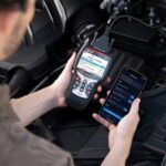
The journey into vehicle data often begins with accessing the CAN bus. One common interface for this is the On-Board Diagnostics II (OBD2) port, which is standard in most modern vehicles. While OBD2 is primarily used for emissions-related diagnostics, it also provides access to a wealth of other vehicle parameters.
Recently, I undertook a project to sniff the raw CAN bus data of a vehicle, and the findings revealed a fascinating landscape of information transmitted via the J1939 protocol. J1939 is a high-speed CAN bus protocol commonly used in heavy-duty vehicles, agricultural equipment, and increasingly in light-duty vehicles for powertrain and other critical systems.
My initial investigation involved connecting to the vehicle’s diagnostic port and capturing the raw CAN bus data. Analyzing this raw data stream required understanding the structure of J1939 messages. In J1939, the message identifier (ID) field is crucial. It defines both the source address of the transmitting module and the Parameter Group Number (PGN), which essentially identifies the type of data being transmitted.
The PGN is a hexadecimal code embedded within the ID. For instance, in an ID like 0CFF6600, the PGN is FF66 (or 65382 in decimal). Online tools like the J1939 Online 29-bit CAN ID to PGN Converter are invaluable for quickly decoding these IDs and extracting the PGN.
Further research using online resources like the ISOBUS Data Dictionary – View PGNAndSPN revealed that PGN 65382 (FF66) is often manufacturer-defined. By observing the data transmitted under this PGN while manipulating the engine, it became clear that this specific PGN was broadcasting engine RPM data.
Examining projects like milodarling/RZR_CAN_HACKS provided insights into how the data is structured within the J1939 messages and how to convert these raw bytes into meaningful values.
Here’s a snippet of the CAN bus data I captured, illustrating various parameters being broadcast:
ID         DLC Data                         Period Count Comment
0CF00400   8   FF FF FF 00 00 FF FF FF      20   169757 Engine Speed from ECU
0CFF6600   8   00 00 FF FF FF FF FF FF      20   169806 RPM First and second bit
10FF6500   8   FF FF FF FF FF FF FF FF     199   16976  Something Polaris Specific
18F00500   8   FF FF FF FF 20 50 FF FF     103   33917  Gear Selection 5th and 6th bit, 20 50 P, 20 52 R, 20 4e N, 20 4c L, 20 48 h ASCII: P
18FDE500   8   0A 14 1E 28 32 3C 78 FA    1002   3394 Max vehicle speed 1-7
18FEC117   8   F8 5F 03 00 10 00 00 00    5003   680  Vehicle distance driven, 5 meters per bit, 4 bytes , trip distance, 5m per bit, 4 bytes
18FECA00   8   40 FF 00 00 00 00 FF FF    1001   3394 Engine OK Signal
18FECA13   8   00 FF 00 00 00 00 FF FF    1001   3306 Code to be read, fault lamp, can indicate data packets, see j1939 spec.
18FEEE00   8   5B FF FF FF FF FF FF FF    1001   3393 Engine Temp? first bit 52=107F 53=109F 54=111F, 55=113F
18FEF100   8   33 00 00 FF FF FF FF FF     100   33885  Vehicle speed
18FEF200   8   00 00 00 FB 00 00 00 FF     100   29966  7th bit throttle position 00-ED, first bit fuel rate
18FEFC17   8   FF B9 FF FF FF FF FF FF    5003   677  Fuel Level Sensor
18FF6713   8   05 7D 00 7D 00 80 3F FF     99   33830  Power Steering
1CEB1700   8   11 2A FF FF FF FF FF FF    2880   49   Polaris?
1CEC1700   8   FF FE FF FF FF DA FE 00     88   6    Polaris?
1CFDDF00   8   FC FF FF FF FF FF FF FF    1000   2407 4wheel drive, 1st bit FC off, FD on DEC: 252 255 255 255 255 255 255 255 ASCII:
1CFF6A00   8   FC FF FF FF FF FF FF FF     501   6743 Polaris?
While tools like Torque Pro offer J1939 support, their customization for manufacturer-specific PGNs can be limited. Exploring alternative apps and diagnostic tools might be necessary to fully decode and utilize all available data. For more advanced applications or when using multiple diagnostic or monitoring tools simultaneously, you might encounter the need to connect several devices to the OBD2 port. This is where an OBD2 splitter becomes invaluable.
An OBD2 splitter allows you to expand a single OBD2 port into multiple ports. This can be particularly useful if you want to use a diagnostic scanner while also having a performance monitor or data logger connected. You can typically find OBD2 splitters at automotive parts retailers. While specific retailers like O’Reilly Auto Parts are popular, many auto parts stores and online marketplaces offer a variety of OBD2 splitters to suit different needs.
For enthusiasts and professionals alike, understanding CAN bus data and utilizing tools to access and interpret it is becoming increasingly important. Whether you’re diagnosing a complex issue, monitoring vehicle performance, or developing custom applications, the ability to tap into your vehicle’s data stream is a powerful asset. As technology advances, exploring these data communication systems will only become more crucial in the automotive landscape.