Understanding the fuse box locations and diagrams in your 2004 Ford F-150 is crucial for diagnosing and resolving electrical issues, especially those related to your OBD2 port. While the original diagrams for the 2004 F-150 detail various fuse locations, pinpointing the fuse related to your OBD2 (On-Board Diagnostics II) port is essential for quick troubleshooting.
This guide provides a comprehensive overview of the fuse box locations in your 2004 Ford F-150 and helps you identify potential fuses that could affect your OBD2 port’s functionality.
Your 2004 Ford F-150 is equipped with three distinct fuse boxes:
Passenger Compartment Fuse Panel
This fuse box is generally the first place to check for issues related to interior electrical components and often includes fuses relevant to the OBD2 port. It is typically located inside the cabin of your F-150.
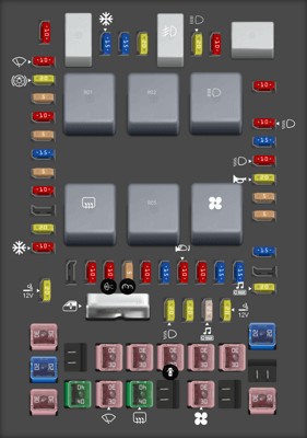
Here is a detailed diagram of the passenger compartment fuse panel:
| Type | No. | Description |
|---|---|---|
| Fuse MINI 10A | 1 | Run/Accessory – Wipers, Instrument cluster |
| Fuse MINI 20A | 2 | Stop/Turn lamps, Speed control deactivate switch |
| Fuse MINI 5A | 3 | Power mirrors, Memory logic power, Memory seats and pedals |
| Fuse MINI 10A | 4 | DVD battery power |
| Fuse MINI 5A | 5 | Keep alive memory for Powertrain Control Module (PCM) and climate control module |
| Fuse MINI 15A | 6 | Parklamps, BSM, Instrument panel illumination |
| Fuse MINI 5A | 7 | Radio (start signal) |
| Fuse MINI 10A | 8 | Heated mirrors, Switch indicator |
| Fuse MINI 20A | 10 | Trailer tow back-up lamps relay (PCB1), Trailer tow parklamp relay (R201) |
| Fuse MINI 10A | 11 | A/C clutch, 4×4 solenoid |
| Fuse MINI 10A | 13 | Climate control module power |
| Fuse MINI 10A | 14 | Back-up lamp and Daytime Running Lamps (DRL) relay coil, A/C pressure switch, Brake-shift interlock solenoid |
| Fuse MINI 5A | 15 | Overdrive cancel, Cluster, Brake-Shift Interlock (BSI) |
| Fuse MINI 10A | 16 | ABS module (Run/Start power) |
| Fuse MINI 15A | 17 | Fog lamp relay (R202) |
| Fuse MINI 10A | 18 | Run/Start feed – Flasher relay, Electrochromatic mirror, Heated seats, BSM, Compass, RSS (Reverse Sensing System) |
| Fuse MINI 10A | 19 | Restraints (Air bag module) |
| Fuse MINI 15A | 20 | PCM 4×4 power |
| Fuse MINI 15A | 21 | Cluster keep alive power |
| Fuse MINI 10A | 22 | Delayed accessory power for audio, power door lock switch and moonroof switch illumination |
| Fuse MINI 10A | 23 | RH low beam headlamp |
| Fuse MINI 15A | 24 | Battery saver power for demand lamps |
| Fuse MINI 10A | 25 | LH low beam headlamp |
| Fuse MINI 20A | 26 | Horn relay (PCB3), Horn power |
| Fuse MINI 5A | 27 | Passenger Air bag Deactivation (PAD) warning lamp, Cluster air bag warning lamp, Cluster RUN /START power |
| Fuse MINI 5A | 28 | SecuriLock transceiver (PATS) |
| Fuse MINI 15A | 29 | PCM 4×4 power |
| Fuse MINI 20A | 31 | Radio power |
| Fuse MINI 15A | 32 | Vapor Management Valve (VMV), A/C clutch relay, Canister vent, Heated Exhaust Gas Oxygen (HEGO) sensors #11 and #21, CMCV, Mass Air Flow (MAF) sensor, VCT |
| Fuse MINI 15A | 33 | Shift solenoid, CMS #12 and #22 |
| Fuse MINI 20A | 34 | Fuel injectors and PCM power |
| Fuse MINI 20A | 35 | Instrument cluster high beam indicator, High beam headlamps |
| Fuse MINI 10A | 36 | Trailer tow right turn/stop lamps |
| Fuse MINI 20A | 37 | Rear power point |
| Fuse MINI 25A | 38 | Subwoofer power |
| Fuse MINI 20A | 39 | Instrument panel power point |
| Fuse MINI 20A | 40 | Low beam headlamps, DRL |
| Fuse MINI 20A | 41 | Cigar lighter, Diagnostic connector power |
| Fuse MINI 10A | 42 | Trailer tow left turn/stop lamps |
| Fuse FMX/JCase 30A | 101 | Starter solenoid |
| Fuse FMX/JCase 20A | 102 | Ignition switch feed |
| Fuse FMX/JCase 20A | 103 | ABS valves |
| Fuse FMX/JCase 30A | 105 | Electric trailer brakes |
| Fuse FMX/JCase 30A | 106 | Trailer tow battery charge |
| Fuse FMX/JCase 30A | 107 | Power door locks (BSM) |
| Fuse FMX/JCase 30A | 108 | Passenger power seat |
| Fuse FMX/JCase 30A | 109 | Driver power seat, Adjustable pedals |
| Fuse FMX/JCase 30A | 111 | 4×4 relays |
| Fuse FMX/JCase 40A | 112 | ABS pump power |
| Fuse FMX/JCase 30A | 113 | Wipers and washer pump |
| Fuse FMX/JCase 40A | 114 | Heated backlite, Heated mirror power |
| Fuse FMX/JCase 30A | 116 | Blower motor |
| Fuse FMX/JCase 30A | 118 | Heated seats |
| Circuit breaker MAXI | 401 | Power windows, Moonroof, Power sliding backlite |
| Relay | R01 | Starter solenoid |
| Relay | R02 | Accessory delay |
| Relay | R03 | Hi-beam headlamps |
| Relay | R04 | Heated backlite |
| Relay | R05 | Trailer tow battery charge |
| Relay | R06 | Blower motor |
| Relay | R201 | Trailer tow park lamps |
| Relay | R202 | Fog lamps |
| Relay | R203 | PCM |
Key Fuses to Check for OBD2 Issues in the Passenger Compartment:
- Fuse #41 (20A): Cigar lighter, Diagnostic connector power: This fuse directly powers the diagnostic connector, which includes your OBD2 port. If your OBD2 scanner is not powering on or connecting, this is the first fuse to inspect.
- Fuse #5 (5A): Keep alive memory for Powertrain Control Module (PCM) and climate control module: The PCM (Powertrain Control Module) is the computer that your OBD2 scanner communicates with. A blown fuse for the PCM’s keep-alive memory could indirectly affect OBD2 communication.
- Fuse #34 (20A): Fuel injectors and PCM power: This is another fuse related to the PCM’s power supply. Check this fuse if you suspect PCM power issues impacting OBD2.
- Fuse #20 & #29 (15A): PCM 4×4 power: These fuses also relate to PCM power, and while primarily for 4×4 systems, PCM power issues can impact OBD2 functionality.
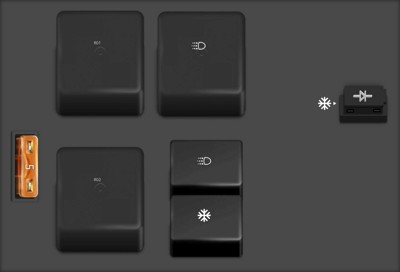
Auxiliary Relay Box (with DRL)
Some 2004 F-150 models are equipped with Daytime Running Lights (DRL). If your vehicle has DRL, it may have this auxiliary relay box.
Here’s the diagram for the auxiliary relay box (with DRL):
| Type | No. | Description |
|---|---|---|
| Fuse ATO 5A | F01 | Clockspring illumination |
| Relay | R01 | 4×4 CCW |
| Relay | R02 | 4×4 CW |
| Relay | R03 | Daytime Running Lamps (DRL) [if equipped, otherwise not used] |
| Relay | R201 | DRL |
| Relay | R202 | A/C clutch |
| Diode ATO | D01 | A/C clutch diode |
OBD2 Relevance: Fuses in this box are less likely to directly affect the OBD2 port, but it’s good to be aware of its location and functions for comprehensive electrical troubleshooting.
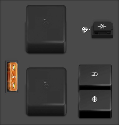
Auxiliary Relay Box (without DRL)
For 2004 F-150 models without Daytime Running Lights, a slightly different auxiliary relay box configuration is used.
Here’s the diagram for the auxiliary relay box (without DRL):
| Type | No. | Description |
|---|---|---|
| Fuse ATO 5A | F01 | Clockspring illumination |
| Relay | R01 | 4×4 CCW |
| Relay | R02 | 4×4 CW |
| Relay | R201 | DRL |
| Relay | R202 | A/C clutch |
| Diode ATO | D01 | A/C clutch diode |
OBD2 Relevance: Similar to the auxiliary relay box with DRL, this box is less likely to house the primary fuse for the OBD2 port itself, but understanding all fuse locations is part of thorough vehicle maintenance.
Conclusion
When troubleshooting OBD2 port issues on your 2004 Ford F-150, start by checking Fuse #41 (20A) “Diagnostic connector power” in the passenger compartment fuse box. If that fuse is intact, investigate the PCM-related fuses in the same box, such as #5, #34, #20, and #29, as power issues to the PCM can also prevent OBD2 communication.
By understanding the locations and diagrams of all three fuse boxes in your 2004 F-150, you can effectively diagnose and address a wide range of electrical problems, including those affecting your OBD2 port. Always refer to your vehicle’s owner’s manual for the most accurate fuse and relay information specific to your truck’s configuration.