Are you interested in accessing your car’s diagnostic data but want to save some money? Creating your own OBD2 to USB cable is a fantastic DIY project that can give you the functionality you need without breaking the bank. This guide will walk you through the process of making a homemade OBD2 to USB cable, allowing you to connect your car to your computer for diagnostics and more.
Disclaimer: Before we begin, please remember that this is a DIY project and should be undertaken at your own risk. I am not a professional mechanic or electronics expert, and this guide is based on my personal experience. While I have successfully created a working cable using these steps, I am not responsible for any damage to your vehicle, computer, or any other unintended consequences. Proceed with caution and ensure you understand each step before proceeding.
Tools and Parts You’ll Need
To get started, gather the following tools and parts. Having everything prepared beforehand will make the process smoother and more efficient.
-
Wire strippers/cutters: Essential for preparing the wires by removing insulation and cutting them to the desired length.
-
Needle-nose pliers: Helpful for manipulating small parts, especially when working with connector pins.
-
Molex crimping tool (optional but recommended): While not strictly necessary, a crimping tool ensures a secure and professional connection between wires and connector pins.
-
Soldering iron (recommended): Soldering provides a robust and reliable electrical connection. If you are comfortable soldering, it’s a highly recommended step.
-
4-pin connector: This connector will serve as the USB interface for your cable. You can find suitable connectors online, such as this 4-pin connector (pin/wire size = 22-16AWG; insulation/seal size = 1.3-1.7mm).
Components of a 4-pin connector kit including pins and housing.
-
OBD-II Cable: You’ll need an OBD-II cable, which you can often find pre-made with a female OBD-II connector and wires. A suitable option is this OBD-II cable.
OBD2 cable showing the connector and multiple wires with shielding removed.
Alternatively, if you have spare wires, you can purchase just the female OBD-II connector and use your own wires to connect to the 4-pin connector. Ensure you select the correct wire size for your 4-pin connector pins.
Step-by-Step Guide: Making Your OBD2 to USB Cable
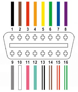
Out of the 16 pins available on the OBD-II connector, we will only be utilizing four essential ones for basic OBD2 to USB functionality:
- Pin 4: Chassis ground (typically an orange wire in the linked OBD2 cable)
- Pin 6: CAN (J-2234) High (typically a green wire in the linked OBD2 cable)
- Pin 14: CAN (J-2234) Low (typically a brown wire with a white stripe in the linked OBD2 cable)
- Pin 16: Battery power (typically a green wire with a white stripe in the linked OBD2 cable)
Let’s begin constructing your homemade OBD2 to USB cable:
Step 1: Prepare the OBD-II Cable
-
Isolate the Necessary Wires: Carefully remove the outer sheath and shielding from the OBD-II cable to access the individual wires. Identify and separate the four wires we will be using: Pin 4 (orange), Pin 6 (green), Pin 14 (brown w/white stripe), and Pin 16 (green w/white stripe).
Four selected wires from an OBD2 cable separated for connection to the 4-pin connector.
-
Prepare Wire Ends: The wires in the OBD-II cable are quite thin (26AWG), while the pins of the 4-pin connector are designed for slightly thicker wires (22AWG). To compensate for this:
- Strip approximately 3/8″ of insulation from the end of each of the four selected wires.
- Fold the exposed wire strands over and twist them to effectively thicken the wire and ensure a better fit within the connector pins.
- Slide a rubber seal (from the 4-pin connector kit) onto each of the prepared wires.
Close-up of a wire end with insulation stripped, wire folded over, and a rubber seal slid onto it.
Step 2: Prepare the 4-Pin Connector Pins
-
Wire Insertion: Examine the pins for the 4-pin connector. You’ll notice two sets of prongs. The front prongs are for securing the wire, and the rear prongs are for securing the rubber seal.
-
Position the Wire: Insert the prepared end of a wire into a pin, ensuring the exposed wire is positioned correctly for the front prongs to clamp onto it. Use needle-nose pliers to hold the wire in place if needed, as the wire may be thin relative to the pin size.
A thin wire inserted into a 4-pin connector pin, showing the size difference.
Step 3: Connect Wires and Solder (or Crimp)
-
Soldering (Recommended): For a strong and reliable connection, soldering is highly recommended. Solder the wire to the pin connector. This is particularly beneficial given the thin gauge of the OBD-II cable wires. If you are new to soldering, there are many helpful resources available online, such as this soldering tutorial video.
Soldered connection of a wire to a connector pin, showcasing a soldered joint.
-
Crimping (Alternative): If you have a Molex crimping tool, use it to crimp the front prongs of the pin connector securely onto the wire. If you don’t have a crimping tool, you can carefully use needle-nose pliers to fold the prongs over the wire. This video on crimping without a dedicated tool can be a useful guide. Crimp one prong at a time, ensuring a tight grip on the wire. You can further secure the connection by gently crushing the prongs a bit more with pliers.
Using pliers to crimp the prongs of a connector pin onto a wire.
Close-up of a connector pin after crimping, showing the prongs folded over and securing the wire.
-
Secure the Seal: Slide the rubber seal up to the back prongs of the pin. Use the same crimping or pliers technique to fold these prongs over the seal, securing it in place and providing strain relief.
Positioning the rubber seal on a connector pin ready to be secured by the back prongs.
Crimping the back prongs of a connector pin over the rubber seal using pliers.
Completed connector pin with both sets of prongs crimped, securing the wire and the rubber seal.
-
Repeat for All Wires: Repeat steps 2 and 3 for the remaining three wires and connector pins.
Step 4: Assemble the 4-Pin Connector
-
Pair and Twist Wires: It’s recommended to twist pairs of wires together to help reduce electromagnetic interference. Pair and twist the wires as follows:
- Pin 4 (orange) with Pin 16 (green w/white stripe)
- Pin 6 (green) with Pin 14 (brown w/white stripe)
(Unfortunately, a photo of the twisted wire pairs is not available.)
-
Insert Pins into Connector Housing: Insert the pins into the 4-pin connector housing in the correct orientation as shown below:
- Pin 14 (brown w/white stripe) > Connector slot A
- Pin 6 (green) > Connector slot B
- Pin 16 (green w/white stripe) > Connector slot C
- Pin 4 (orange) > Connector slot D
Push each pin into the rear of the connector housing until you hear a click, indicating it is locked securely in place. You can use needle-nose pliers to gently pull the wire from the back to ensure the pin is locked.
Diagram showing the pinout for the 4-pin connector with wire color assignments.
Step 5: Test Your Homemade Cable
Congratulations! You have now completed your homemade OBD2 to USB cable.
Finished homemade OBD2 to USB cable with 4-pin and OBD2 connectors.
The completed DIY OBD2 to USB cable connected for testing purposes.
Connect your new cable to your car’s OBD2 port and your computer to test its functionality with your preferred diagnostic software.
Screenshot showing successful connection and error clearing using the DIY OBD2 to USB cable.
This homemade OBD2 to USB cable should now allow you to read diagnostic trouble codes, monitor vehicle parameters, and perform other OBD2 functions. If you encounter any issues or have questions, review each step and double-check your connections. Enjoy the convenience of diagnosing your car with your DIY cable!