Connecting to your car’s On-Board Diagnostics II (OBD2) system opens up a world of possibilities for monitoring performance, diagnosing issues, and customizing your vehicle. For DIY enthusiasts and professionals alike, the OBD2 port is a gateway to valuable data. Often, this connection involves a DB9 connector, particularly when interfacing with CAN bus systems. However, setting up a reliable Obd2 Db9 link isn’t always straightforward. Many users, especially those new to automotive electronics and protocols like CAN bus, encounter frustrating roadblocks when trying to read data like engine RPM or vehicle speed.
This guide is designed to help you troubleshoot common issues you might face when working with OBD2 and DB9 connectors. We’ll explore potential problems, from basic wiring mistakes to more complex CAN bus communication challenges, and provide actionable steps to get your OBD2 DB9 connection working smoothly. Whether you’re using an Arduino with a CAN bus shield, a dedicated OBD2 adapter, or building your own interface, this article will equip you with the knowledge to diagnose and resolve connectivity problems.
Understanding the Basics: OBD2, CAN Bus, and DB9
Before diving into troubleshooting, let’s clarify some fundamental concepts. OBD2 (On-Board Diagnostics II) is a standardized system used in most modern vehicles to provide access to vehicle subsystem information. This standard mandates a 16-pin J1962 connector in the vehicle. While the OBD2 port itself is standardized, the communication protocols used over it can vary, with CAN bus (Controller Area Network) being one of the most prevalent, especially for in-vehicle networks.
The DB9 connector, on the other hand, is not part of the OBD2 standard itself. Instead, DB9 connectors are frequently used in aftermarket OBD2 adapters and DIY projects as a robust and accessible interface for CAN bus communication signals. Think of the DB9 as a convenient breakout point that allows you to tap into the CAN High and CAN Low signals from your OBD2 port for use with microcontrollers, computers, or other diagnostic equipment.
[Alt text: Oscilloscope trace showing rapid CAN bus message transmission, potentially indicating a problem with data request or response handling in an OBD2 DB9 setup. ]
Common Challenges with OBD2 to DB9 Connections
Many DIYers and even experienced technicians can stumble when setting up an OBD2 to DB9 connection. Here are some typical issues:
- Incorrect DB9 Wiring: The most frequent culprit is incorrect wiring of the OBD2 to DB9 cable. A single misplaced wire can prevent communication entirely. Different sources online might offer conflicting wiring diagrams, leading to confusion.
- CAN Bus Shield Configuration Errors: If you’re using a CAN bus shield with a microcontroller like Arduino, incorrect configuration of the shield is a common problem. This includes issues with baud rate settings, chip select (CS) pin assignments, and library initialization.
- Software and Code Issues: The code used to request and interpret OBD2 data plays a crucial role. Errors in the code, such as incorrect PID (Parameter ID) requests, improper CAN message formatting, or flawed data parsing, can lead to no data or garbled readings.
- Hardware Malfunctions: While less common, hardware failures can occur. A faulty CAN bus shield, a damaged DB9 connector, or issues within the vehicle’s OBD2 port itself can prevent successful communication.
- Protocol Mismatches: While CAN bus is common, some vehicles might use different OBD2 protocols. Although less likely to be the primary issue with a basic DB9 CAN interface, protocol mismatches can become relevant in more advanced diagnostic scenarios.
Step-by-Step Troubleshooting Guide
Let’s systematically address these potential problems to get your OBD2 DB9 connection working.
1. Verify Your OBD2 to DB9 Cable Wiring – The Foundation of Your Connection
The wiring of your OBD2 to DB9 cable is paramount. Double and triple-check your wiring against reliable sources. A common and generally accepted OBD2 to DB9 wiring for CAN bus communication is as follows (always verify against your specific application and hardware documentation):
- OBD2 Pin 6 (CAN High) to DB9 Pin 7 (CAN High)
- OBD2 Pin 14 (CAN Low) to DB9 Pin 2 (CAN Low)
- OBD2 Pin 4 (Ground) and/or Pin 5 (Signal Ground) to DB9 Pin 3 (Ground) (Connect at least one ground pin)
- OBD2 Pin 16 (Battery Power) (Optional, often needed for active adapters)
Action Steps:
- Consult Multiple Wiring Diagrams: Don’t rely on a single source. Search for “OBD2 DB9 CAN bus wiring diagram” and compare several diagrams. Reputable automotive or electronics forums and documentation for your CAN shield are good starting points.
- Use a Multimeter for Continuity Testing: After wiring your cable, use a multimeter in continuity mode to verify each connection. Ensure that the correct pins are connected and that there are no shorts between pins that shouldn’t be connected.
- Inspect Connectors: Visually inspect both the OBD2 and DB9 connectors for bent pins, damage, or loose wires.
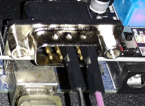
[Alt text: Close-up of a DIY OBD2 to DB9 cable with color-coded wires, highlighting the importance of precise wiring for successful CAN bus communication in automotive diagnostics. ]
2. Check Your CAN Bus Shield and Arduino Configuration
If you’re using an Arduino with a CAN bus shield (like the Seeed CAN Shield V2.0 mentioned in the original post), ensure it’s correctly configured.
Action Steps:
- Verify Shield Compatibility: Double-check that your CAN bus shield is compatible with your Arduino board and intended for OBD2 CAN bus communication.
- Set the Correct Baud Rate: CAN bus in OBD2 typically operates at 500 kbps. Make sure your CAN bus shield library and initialization code are set to this baud rate. Incorrect baud rate is a frequent cause of communication failure.
- Pin Assignments (CS, INT): Confirm the Chip Select (CS) pin and interrupt (INT) pin assignments in your code match how your CAN bus shield is physically connected to your Arduino. For the Seeed CAN Shield V2.0, the CS pin is often D9, but always verify your specific shield’s documentation.
- Library Initialization: Ensure you’ve correctly included and initialized the CAN bus library in your Arduino code. Refer to the library’s examples and documentation for proper setup. For MCP2515-based shields (common for Arduino CAN shields), libraries like
mcp_can.hare frequently used.
3. Review and Test Your Code – Sending the Right Messages
The code you use to communicate with the OBD2 system must be accurate.
Action Steps:
- Start with Example Code: Begin with well-tested example code for your CAN bus shield and OBD2 interaction. Libraries often provide examples for reading common PIDs like engine RPM and vehicle speed. The original post mentions using examples from the Seeed CAN Shield library, which is a good starting point.
- Verify PIDs (Parameter IDs): Ensure you are using the correct PIDs for the data you want to read. PIDs are standardized codes that request specific information from the vehicle’s ECU (Engine Control Unit). Common PIDs like
0x0C(Engine RPM) and0x0D(Vehicle Speed) are often used for initial testing. - CAN Message Structure: Understand the structure of CAN messages used for OBD2 requests and responses. OBD2 requests typically use CAN ID
0x7DF, and responses come back with IDs in the range0x7E8to0x7EF. Your code needs to correctly format the request messages and parse the response messages. - Implement Error Handling: Add error handling to your code to detect and report CAN bus communication errors. This can help you identify if the issue is at the hardware level or within the data interpretation.
- Address “Spamming” Issue: The original poster observed the CAN shield “spamming” messages. This could indicate that the shield is continuously re-transmitting requests because it’s not receiving valid responses. Properly implement request-response logic in your code, including delays and checks for incoming messages before resending.
[Alt text: A breadboard setup possibly showing an Arduino with a CAN bus shield and OBD2 DB9 cable, illustrating a typical DIY environment for automotive diagnostic projects and highlighting potential points of failure. ]
4. Utilize an Oscilloscope for CAN Bus Signal Analysis
An oscilloscope is an invaluable tool for diagnosing CAN bus communication issues at the signal level.
Action Steps:
- Check for Signal Presence: Connect your oscilloscope probes to the CAN High (DB9 Pin 7) and CAN Low (DB9 Pin 2) pins while your system is attempting to communicate. You should see activity on the CAN bus when requests are being sent. The oscilloscope image in the original post shows some activity, but it might not be correct or properly formed CAN signals.
- Verify Signal Levels: CAN bus uses differential signaling. CAN High should typically swing higher and CAN Low lower relative to a common mode voltage. Consult CAN bus specifications for voltage level expectations.
- Look for Signal Integrity Issues: Check for signal reflections, ringing, or excessive noise on the CAN bus signals. These signal quality problems can disrupt communication. Termination resistors (120 ohms) at each end of the CAN bus are often necessary to maintain signal integrity, especially in longer or more complex CAN bus setups. For simple OBD2 connections, termination is often built into the vehicle or adapter.
5. Test with a Known Good OBD2 Scanner
Before assuming the problem lies entirely with your DIY setup, test your vehicle’s OBD2 port with a commercially available OBD2 scanner.
Action Steps:
- Use a Standard OBD2 Scanner: Plug a known working OBD2 scanner into your vehicle’s OBD2 port.
- Verify Basic Functionality: Confirm that the scanner can successfully connect to your vehicle and read basic data like engine codes or live parameters. If a standard scanner also fails to connect, the issue might be with your vehicle’s OBD2 port or ECU, not your DB9 setup.
Advanced Considerations
- CAN Bus Termination: While often less critical for short OBD2 connections, CAN bus termination resistors (120 ohms) might be needed in some cases, especially if you are extending the CAN bus wiring or experiencing signal integrity problems.
- Vehicle Compatibility: While OBD2 is a standard, there can be subtle variations between vehicle makes and models. Some vehicles might have more complex CAN bus implementations or require specific initialization sequences.
- Power Supply: Ensure your CAN bus shield and any active components in your OBD2 DB9 adapter are properly powered. Some adapters require power from the OBD2 port (Pin 16), while others might need an external power source.
Conclusion
Troubleshooting OBD2 DB9 connection problems requires a systematic approach. By meticulously checking your wiring, CAN bus shield configuration, code, and using tools like a multimeter and oscilloscope, you can isolate and resolve the root cause of your connectivity issues. Remember to start with the basics, verify each component step-by-step, and utilize available resources and example code. With patience and careful debugging, you’ll be able to unlock the wealth of data available through your vehicle’s OBD2 port and bring your automotive projects to life.