Maintaining your 2000 Ford F-150 means understanding its electrical system, and a key part of that is knowing your fuse box locations and diagrams. If you’re experiencing issues with your OBD2 port or other electrical components, checking the fuses is a crucial first step. This guide will walk you through the fuse box locations and diagrams for your 2000 Ford F-150, helping you pinpoint the right fuse for your OBD2 port and other systems.
Your 2000 Ford F-150 is equipped with two distinct fuse boxes. Knowing where they are and what they control is essential for effective troubleshooting. Let’s explore each location and its corresponding fuse diagram.
Passenger Compartment Fuse Panel
The primary fuse box, known as the passenger compartment fuse panel, is located inside the vehicle. This fuse box is responsible for many of the interior electrical functions of your F-150.
Passenger compartment fuse panel diagram
| Fuse Number | Fuse Type | Ampere Rating | Description |
|---|---|---|---|
| 1 | MINI | 15A | Audio |
| 2 | MINI | 5A | Powertrain Control Module (PCM), Cluster |
| 3 | MINI | 20A | Cigar Lighter, OBD-II Scan Tool Connector |
| 4 | MINI | 5A | Remote Entry Module, Mirrors |
| 5 | MINI | 15A | Speed Control Module, Reverse Lamp, Climate Mode Switch, Daytime Running Lamp Relay |
| 6 | MINI | 5A | Cluster, Brake Shift Interlock Solenoid, GEM Module |
| 8 | MINI | 5A | Radio, Remote Entry Module, GEM Module |
| 11 | MINI | 30A | Front Washer Pump Relay, Wiper Run/Park Relay, Wiper Hi/LO Relay, Windshield Wiper Motor |
| 13 | MINI | 20A | Stop Lamp Switch (Lamps), Turn/Hazard Flasher, Speed Control Module |
| 14 | MINI | 15A | Battery Saver Relay, Interior Lamp Relay, Accessory Delay Relay (Power Windows) |
| 15 | MINI | 5A | Stop Lamp Switch, (Speed Control, Brake Shift Interlock, ABS, PCM Module Inputs), GEM Module, RABS Test Connector |
| 16 | MINI | 20A | Headlamps (Hi Beams), Cluster (Hi Beam Indicator) |
| 18 | MINI | 5A | Instrument Illumination (Dimmer Switch Power) |
| 20 | MINI | 5A | Audio, GEM (or CTM) Module, Powertrain Control Module (PCM) |
| 21 | MINI | 15A | Starter Relay, Clutch Switch, Fuse 20 |
| 22 | MINI | 10A | Air Bag Module, Passenger Airbag Deactivation Module, Climate Mode Switch (Blower Relay) |
| 23 | MINI | 10A | Trailer Tow Battery Charge Relay, Turn/Hazard Flasher, 4×4 Solenoids, 4×4 Relays, Overhead Console, 4 Wheel Anti-Lock Brake System (4WABS) Module |
| 26 | MINI | 10A | Right Side Low Beam Headlamp |
| 27 | MINI | 5A | Foglamp Relay and Foglamp Indicator |
| 28 | MINI | 10A | Left Side Low Beam Headlamp |
| 29 | MINI | 5A | Autolamp Module, Transmission Overdrive Control Switch |
| 30 | MINI | 30A | Passive Anti Theft Transceiver, Cluster, Ignition Coils, Powertrain Control Module Relay |
| R1 | Relay | – | Interior Lamp Relay |
| R2 | Relay | – | Battery Saver Relay |
| R4 | Relay | – | One Touch Down Window Relay |
| R5 | Relay | – | ACC Delay Relay |
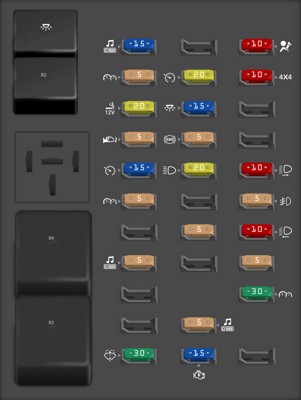
Locating the OBD2 Fuse: For your 2000 Ford F-150, the fuse specifically related to the OBD-II (On-Board Diagnostics II) scan tool connector is Fuse #3 in the passenger compartment fuse panel. This fuse is a 20A MINI fuse and is also shared with the cigar lighter. If you are experiencing issues connecting your OBD2 scanner, or if your cigar lighter is not working, this fuse should be one of the first things you check. A blown fuse here can prevent your scanner from powering up or communicating with your vehicle’s computer.
Power Distribution Box
The second fuse box is the power distribution box, often referred to as the engine compartment fuse box. This box is located under the hood and houses fuses and relays for high-power systems and engine-related components.
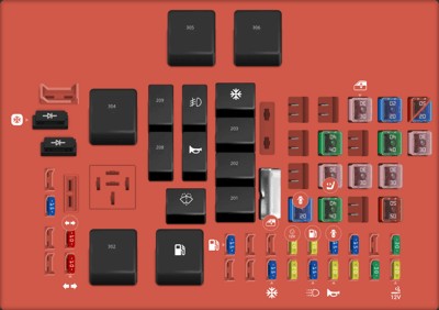
Power distribution box diagram
| Fuse Number | Fuse Type | Ampere Rating | Description |
|---|---|---|---|
| 1 | MINI | 20A | Power Point |
| 2 | MINI | 30A | Powertrain Control Module |
| 3 | MINI | 30A | Headlamps/Autolamps |
| 5 | MINI | 20A | Trailer Tow Backup/Park Lamps |
| 6 | MINI | 15A | Parklamps/Autolamps, Passenger Fuse Panel Feed Fuse #18 |
| 7 | MINI | 20A | Horn |
| 8 | MINI | 15A | Power Door Locks |
| 9 | MINI | 15A | Daytime Running Lamps (DRL), Fog Lamps |
| 10 | MINI | 20A | Fuel Pump |
| 11 | MINI | 20A | Alternator Field |
| 12 | MINI | 20A | Rear Auxiliary Power Point |
| 13 | MINI | 15A | A/C Clutch |
| 18 | MINI | 15A | Powertrain Control Module, Fuel Injectors, Fuel Pump Relay, Idle Air Control, Mass Air Flow Sensor |
| 19 | MINI | 10A | Trailer Tow Stop and Right Turn Lamp |
| 20 | MINI | 10A | Trailer Tow Stop and Left Turn Lamp |
| 23 | MINI | 15A | HEGO Sensor, Canister Vent, Automatic Transmission, CMS Sensor |
| 101 | FMX/JCase | 30A | Trailer Tow Battery Charge |
| 102 | FMX/JCase | 50A | Four Wheel Antilock Brake Module |
| 102 | FMX/JCase | 20A | Rear Wheel Antilock Brake Module |
| 103 | FMX/JCase | 50A | Junction Block Battery Feed |
| 104 | FMX/JCase | 30A | 4×4 Shift Motor & Clutch |
| 105 | FMX/JCase | 40A | Climate Control Front Blower |
| 106 | FMX/JCase | 20A | Inter Cooler Pump [Lightning only] |
| 108 | FMX/JCase | 30A | Trailer Tow Electric Brake |
| 110 | FMX/JCase | 30A | Power Windows |
| 111 | FMX/JCase | 40A | Ignition Switch Battery Feed (Start and Run Circuits) |
| 112 | FMX/JCase | 30A | Drivers Power Seat, Adjustable Pedals |
| 113 | FMX/JCase | 40A | Ignition Switch Battery Feed (Run and Accessory Circuits) |
| 115 | FMX/JCase | 20A | Power Door Locks [SuperCrew only] |
| 201 | Relay | – | Trailer Tow Park Lamp Relay |
| 202 | Relay | – | Front Wiper Run/Park Relay |
| 203 | Relay | – | Trailer Tow Backup Lamp Relay |
| 204 | Relay | – | A/C Clutch Relay |
| 205 | Relay | – | Horn Relay |
| 206 | Relay | – | Fog Lamp Relay |
| 207 | Relay | – | Front Washer Pump Relay |
| 208 | Relay | – | Inter Cooler Pump Relay [Lightning only] |
| 209 | Relay | – | Front Wiper Hi/Lo Relay |
| 301 | Relay | – | Fuel Pump Relay |
| 302 | Relay | – | Trailer Tow Battery Charge Relay |
| 304 | Relay | – | Powertrain Control Module Relay |
| 305 | Relay | – | Fuel Pump Hi/Lo Relay [Lightning only] |
| 306 | Relay | – | Inertia Switch Relay [Lightning only] |
| 501 | Diode ATO | – | Powertrain Control Module Diode |
| 502 | Diode ATO | – | A/C Compressor Diode |
| 601 | Circuit breaker MAXI | – | Power Windows, Moonroof [SuperCrew only] |
Using Fuse Diagrams for Troubleshooting: When diagnosing electrical issues in your 2000 Ford F-150, these fuse diagrams are invaluable tools. Always refer to the correct diagram for your vehicle year, as fuse box layouts can change between model years. To troubleshoot an issue, identify the circuit you suspect is causing the problem, locate the corresponding fuse in the diagram, and then check the fuse in the actual fuse box.
Important Notes on Fuses:
- Fuse Type and Rating: Ensure you replace a blown fuse with one of the same type and ampere rating. Using a fuse with a higher rating can damage the electrical system.
- Visual Inspection: A blown fuse can often be identified by a broken wire inside the fuse housing.
- Fuse Puller: Use a fuse puller tool (often found in one of the fuse boxes) to safely remove fuses.
- Consult a Professional: If you are unsure about diagnosing or repairing electrical issues, it’s always best to consult a qualified mechanic.
By understanding the fuse box locations and diagrams for your 2000 Ford F-150, and specifically knowing the 2000 Ford F150 Obd2 Fuse Location (Fuse #3 in the passenger compartment), you can confidently begin troubleshooting many common electrical problems and keep your truck running smoothly.