Understanding your vehicle’s On-Board Diagnostics (OBD2) system is crucial for modern car maintenance and diagnostics. This guide will provide a comprehensive overview of the OBD2 system, with a particular focus on the Obd2 Power Supply Pin, specifically pin 16, and its vital role in powering your diagnostic tools.
What is OBD2 and Why is the Power Supply Pin Important?
OBD2 is a standardized system in vehicles that allows access to diagnostic information. It’s how mechanics and car enthusiasts can read trouble codes, monitor real-time data, and understand the health of a vehicle’s engine and related systems. At the heart of this system is the 16-pin OBD2 connector, typically located within easy reach of the driver’s seat.
The OBD2 power supply pin, pin 16, is essential because it provides the voltage necessary to power external OBD2 devices like scanners, code readers, and data loggers. Without a functioning power supply from pin 16, these tools would be unable to communicate with your car’s computer and retrieve diagnostic information.
Does Your Car Have an OBD2 Connector and Power Supply Pin?
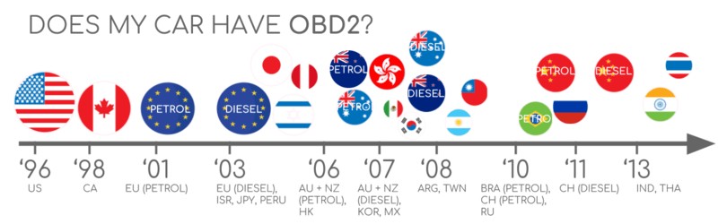
The good news is that if you own a car manufactured after the mid-1990s, it almost certainly has an OBD2 port. Legislation in the United States mandated OBD2 for cars and light trucks in 1996, with similar adoption timelines globally in the early 2000s. While older cars might have a 16-pin connector that resembles OBD2, it may not be fully compliant.
Here’s a quick guide to OBD2 adoption based on region and vehicle type:
- 1996: OBD2 mandatory in the USA for cars/light trucks.
- 2001: Required in the EU for gasoline cars (EOBD).
- 2003: Required in the EU for diesel cars (EOBD).
- 2005: OBD2 required in the US for medium-duty vehicles.
- 2008: US cars must use ISO 15765-4 (CAN) as the OBD2 communication basis.
- 2010: OBD2 required in US heavy-duty vehicles.
To check if your car is OBD2 compliant, you can typically refer to your vehicle’s manual or look for an OBD2 compliance sticker, often found under the hood. The presence of a 16-pin connector near the steering wheel is a strong indicator, but confirming the year and region of manufacture provides further certainty.
A Brief History of OBD2 and its Standardization
The origin of OBD2 can be traced back to California, with the California Air Resources Board (CARB) requiring OBD systems in new cars from 1991 onwards for emissions monitoring. The Society of Automotive Engineers (SAE) played a crucial role in standardizing OBD2, leading to the SAE J1962 standard which defined the 16-pin OBD2 connector and standardized Diagnostic Trouble Codes (DTCs) across different vehicle manufacturers. This standardization was a game-changer, allowing for greater interoperability of diagnostic tools and simplifying vehicle repair.
The Future of OBD2: OBD3 and Beyond
While OBD2 remains a vital standard, the automotive landscape is evolving. Electric vehicles (EVs), for example, often don’t fully adhere to OBD2 standards for diagnostics, instead relying on OEM-specific protocols like UDS (Unified Diagnostic Services). This shift presents challenges for accessing data from EVs using standard OBD2 tools.
Looking ahead, concepts like OBD3 are being discussed, envisioning telematics integration for remote diagnostics and emissions monitoring. This could involve vehicles automatically transmitting diagnostic data wirelessly, streamlining inspections and potentially enabling proactive maintenance. However, concerns around data privacy and manufacturer control over vehicle data are also part of the ongoing conversation. The German car industry, for example, has expressed interest in limiting third-party access to OBD2 data, emphasizing its original purpose for repair shops and not for creating a data-driven economy.
OBD2 Standards: Connector, Protocols, and the Power Supply Pin
OBD2 operates as a higher-layer protocol, similar to a language, built upon lower-layer communication methods like CAN (Controller Area Network) bus. This is analogous to other CAN-based protocols like J1939, CANopen, and NMEA 2000. The OBD2 standards encompass various aspects, including the OBD2 connector, communication protocols, and Parameter IDs (PIDs).
The standards are organized using a 7-layer OSI model framework, with both SAE and ISO standards contributing. SAE standards often reflect US-centric OBD definitions, while ISO standards are prevalent in Europe. Many standards are technically equivalent, like SAE J1979 and ISO 15031-5 for diagnostic services, and SAE J1962 and ISO 15031-3 for the OBD connector.
Deep Dive: The OBD2 Connector and Pin 16 Power Supply [SAE J1962]
The 16-pin OBD2 connector, defined by SAE J1962 / ISO 15031-3, is the physical interface for accessing vehicle data. Pin 16 is specifically designated as the battery power supply pin.
Here are key points about the OBD2 connector and pin 16:
- Location: Typically located under the dashboard, near the steering column, though its exact location can vary and may be somewhat hidden.
- Pin 16 – Power Supply: Provides battery voltage, usually 12V for passenger cars (Type A connector) and 24V for trucks and heavy-duty vehicles (Type B connector). This power is often available even when the ignition is switched off.
- Pinout Variations: The function of other pins can vary depending on the communication protocol used by the vehicle.
- CAN Bus Connection: In modern vehicles using CAN bus for OBD2 communication, pins 6 (CAN-High) and 14 (CAN-Low) are crucial for data transmission.
OBD2 Connector Types: Type A vs. Type B and Power Considerations
You might encounter two main types of OBD2 connectors: Type A and Type B. Type A is standard in cars and light-duty vehicles, while Type B is more common in medium and heavy-duty vehicles. Both types share a similar pinout, but a key difference lies in the power supply output. Type A typically provides 12V, while Type B provides 24V. Baud rates can also differ, with cars often using 500K and heavy-duty vehicles often using 250K (though 500K support is increasing).
Visually, Type B connectors have a distinguishing interrupted groove in the middle, making them incompatible with Type A adapters. However, Type B OBD2 adapter cables are generally designed to be backward compatible with both Type A and Type B sockets.
OBD2 Communication over CAN Bus and ISO 15765-4
Since 2008, CAN bus has been the mandated lower-layer protocol for OBD2 in US vehicles, as per ISO 15765. ISO 15765-4, also known as Diagnostics over CAN (DoCAN), specifies how OBD2 operates on a CAN network. It imposes restrictions on the CAN standard (ISO 11898) to ensure compatibility for diagnostic equipment.
Key aspects of ISO 15765-4 include:
- CAN Bit-rate: Must be 250K or 500K.
- CAN IDs: Supports both 11-bit and 29-bit CAN identifiers.
- Standardized CAN IDs: Specific CAN IDs are reserved for OBD requests and responses.
- Data Length: Diagnostic CAN frames must have a data length of 8 bytes.
- Cable Length Limit: OBD2 adapter cables should not exceed 5 meters.
CAN Identifiers for OBD2 Communication: 11-bit and 29-bit
OBD2 communication relies on request and response message exchanges. In most cars, 11-bit CAN IDs are used. The ‘Functional Addressing’ ID 0x7DF is commonly used to broadcast a request to all OBD2-compliant ECUs (Electronic Control Units). ‘Physical Addressing’ IDs (0x7E0-0x7E7) can target specific ECUs, though are less frequently used.
ECU responses typically use 11-bit IDs in the range 0x7E8-0x7EF. 0x7E8 is the most common response ID, usually originating from the ECM (Engine Control Module), and 0x7E9 from the TCM (Transmission Control Module).
Some vehicles, particularly vans and medium/heavy-duty vehicles, may utilize extended 29-bit CAN identifiers for OBD2. In this case, the ‘Functional Addressing’ CAN ID is 0x18DB33F1. Responses are sent with CAN IDs ranging from 0x18DAF100 to 0x18DAF1FF, often seen as J1939 PGN 0xDA00 (55808).
OBD2 vs. OEM-Specific CAN Protocols: Understanding the Difference
It’s important to recognize that OBD2 is an additional protocol layered on top of a vehicle’s core communication network. Vehicle ECUs primarily function using proprietary CAN protocols defined by the Original Equipment Manufacturer (OEM). These OEM protocols are often specific to the vehicle brand, model, and year and are typically not publicly documented (requiring reverse engineering to understand).
When you connect an OBD2 tool, you are generally interacting with the OBD2 protocol layer, which is designed for diagnostics and emissions-related data. While you might observe OEM-specific CAN data on the same network, especially when connecting a CAN bus data logger to the OBD2 port, accessing and interpreting this data usually requires specialized knowledge and tools. In many newer vehicles, a gateway system might restrict access to OEM CAN data through the OBD2 port, allowing only OBD2 communication.
Think of OBD2 as a diagnostic ‘side channel’ running alongside the vehicle’s main communication network.
Verifying Bit-rate and CAN ID Configuration
OBD2 over CAN can use two bit-rates (250K, 500K) and two CAN ID lengths (11-bit, 29-bit), resulting in four possible combinations. Modern cars commonly use 500K and 11-bit IDs. Diagnostic tools should ideally perform an auto-detection process to identify the correct configuration.
ISO 15765-4 outlines a procedure for automatically detecting the correct bit-rate and CAN ID configuration. This process typically involves sending a mandatory OBD2 request and checking for a valid response. Incorrect bit-rate settings will result in CAN error frames, allowing the tool to systematically test different configurations.
Newer versions of ISO 15765-4 also account for vehicles that might support OBD communication via OBDonUDS (OBD on Unified Diagnostic Services) instead of the more traditional OBDonEDS (OBD on Emission Diagnostic Service). Tools might send UDS requests to identify vehicles using OBDonUDS. However, OBDonEDS (also known as OBD2, SAE OBD, EOBD, or ISO OBD) remains the prevalent standard in most non-EV cars, while WWH-OBD/OBDonUDS is primarily used in EU trucks and buses.
Legacy OBD2 Protocols: Beyond CAN Bus
While CAN bus is dominant today, older vehicles (pre-2008) might use one of five lower-layer protocols for OBD2. Understanding these legacy protocols can be helpful when working with older cars. The OBD2 connector pinout can sometimes provide clues about the protocol in use.
The five protocols are:
- ISO 15765 (CAN bus): Mandatory in US cars since 2008, now widely used.
- ISO 14230-4 (KWP2000): Keyword Protocol 2000, common in 2003+ Asian cars.
- ISO 9141-2: Used in EU, Chrysler, and Asian cars in 2000-2004.
- SAE J1850 (VPW): Variable Pulse Width Modulation, primarily in older GM cars.
- SAE J1850 (PWM): Pulse Width Modulation, primarily in older Ford cars.
ISO-TP and OBD2 Message Transport [ISO 15765-2]
OBD2 messages on CAN bus are transported using ISO-TP (ISO 15765-2), a transport protocol. ISO-TP enables the transmission of data payloads exceeding the 8-byte limit of a standard CAN frame. This is essential for OBD2 functions like retrieving the Vehicle Identification Number (VIN) or Diagnostic Trouble Codes (DTCs), which often require more than 8 bytes of data. ISO-TP handles segmentation, flow control, and reassembly of these larger messages.
For smaller OBD2 data exchanges that fit within a single CAN frame, ISO 15765-2 utilizes ‘Single Frame’ (SF) messages. In a Single Frame, the first byte (PCI field) indicates the payload length, leaving 7 bytes for OBD2-specific data.
Decoding the OBD2 Diagnostic Message [SAE J1979, ISO 15031-5]
A simplified OBD2 message on CAN bus consists of a CAN identifier, a data length indicator (PCI field), and the data payload. The payload itself is structured into: Mode, Parameter ID (PID), and data bytes.
OBD2 Request and Response Example: Vehicle Speed
Consider an example of requesting ‘Vehicle Speed’ (PID 0x0D). A diagnostic tool sends a request message with CAN ID 0x7DF and a 2-byte payload: Mode 0x01 and PID 0x0D. The vehicle responds with CAN ID 0x7E8 and a 3-byte payload, including the speed value in the fourth byte (e.g., 0x32, which is 50 in decimal). By consulting OBD2 PID documentation, you can determine that 0x32 corresponds to 50 km/h.
The 10 OBD2 Diagnostic Services (Modes)
OBD2 defines 10 diagnostic services, also referred to as modes. Mode 0x01 is used to request current real-time data, while other modes are for accessing DTCs, freeze frame data, and clearing codes. Vehicles are not required to support all 10 modes, and manufacturers can also implement OEM-specific modes beyond the standard set.
In OBD2 messages, the mode is the second byte in the data payload. In a request message, the mode is included directly (e.g., 0x01). In a response, 0x40 is added to the requested mode value (e.g., a response to mode 0x01 will start with mode 0x41).
OBD2 Parameter IDs (PIDs) and the Essential PID 0x00
Within each OBD2 mode, Parameter IDs (PIDs) are used to specify the data being requested. Mode 0x01, for instance, includes approximately 200 standardized PIDs for real-time data like speed, RPM, and fuel level. However, vehicles typically support only a subset of these PIDs.
PID 0x00 in mode 0x01 is a special case. If an ECU supports any OBD2 services, it must support mode 0x01 PID 0x00. When requested, the ECU responds indicating which PIDs in the range 0x01-0x20 it supports. This makes PID 0x00 a fundamental test for OBD2 compatibility. PIDs 0x20, 0x40, 0x60, etc., are used similarly to determine support for subsequent PID ranges within mode 0x01.
OBD2 PID Overview Tools
SAE J1979 and ISO 15031-5 appendices detail the scaling and units for standard OBD2 PIDs, allowing you to convert raw data into physical values. Online OBD2 PID lookup tools can be invaluable for quickly referencing PID information and constructing request frames.
OBD2 PID overview tool
Practical Guide: Logging and Decoding OBD2 Data
Let’s look at a practical example of logging OBD2 data using a CAN bus data logger like the CANedge. CANedge devices can be configured to transmit custom CAN frames, making them suitable for sending OBD2 requests.
Step #1: Validate Bit-rate, CAN IDs, and Supported PIDs
Before logging, it’s crucial to verify the correct bit-rate, CAN IDs, and identify the PIDs supported by your vehicle. Using a tool like CANedge, you can:
- Test bit-rate: Send a CAN frame at 500K and check for successful transmission. If unsuccessful, try 250K.
- Use the validated bit-rate for subsequent communication.
- Send ‘Supported PIDs’ requests (mode 0x01, PID 0x00) and analyze the responses.
- Determine 11-bit or 29-bit CAN IDs based on response IDs.
- Identify supported PIDs based on response data.
Pre-configured CANedge configurations can simplify these tests. Most post-2008 non-EV cars support 40-80 PIDs using 500K bit-rate, 11-bit CAN IDs, and the OBD2/OBDonEDS protocol. Tools like asammdf can be used to review responses and decode ‘Supported PIDs’ data using OBD2 PID lookup tools.
Review supported PIDs via OBD2 lookup tool
Step #2: Configure OBD2 PID Requests for Logging
Once you’ve identified supported PIDs, configure your data logger to send requests for the PIDs you want to log. Consider these points:
- CAN IDs: Use ‘Physical Addressing’ request IDs (e.g., 0x7E0) to target specific ECUs and minimize redundant responses.
- Request Spacing: Introduce delays of 300-500ms between requests to avoid overwhelming ECUs.
- Battery Drain: Implement triggers to stop requests when the vehicle is inactive to prevent battery drain. Remember, the OBD2 power supply pin (pin 16) can provide power even when the ignition is off.
- Filters: Apply filters to record only relevant OBD2 response messages, especially if OEM-specific CAN data is also present.
With these settings, your data logger is ready to record raw OBD2 data.
obd2-transmit-list-example-canedge
Step #3: DBC Decode Raw OBD2 Data for Analysis
To analyze logged data, you need to decode the raw OBD2 data into meaningful physical values. Decoding information is available in ISO 15031-5/SAE J1979 and online resources. A free OBD2 DBC file simplifies this process, enabling DBC decoding in CAN bus analysis software.
Decoding OBD2 data is more complex than standard CAN signals because different PIDs share the same CAN ID (e.g., 0x7E8). Therefore, decoding requires considering not only the CAN ID but also the OBD2 mode and PID. This ‘extended multiplexing’ is handled in specialized DBC files.
OBD2 data decoded visual plot asammdf CAN bus DBC file
CANedge: A Practical OBD2 Data Logger Solution
The CANedge is a robust tool for logging OBD2 data directly to an SD card (8-32GB). Its ease of use and compatibility with free software and an OBD2 DBC file make it a valuable asset for OBD2 data acquisition.
OBD2 logger intro CANedge
Multi-Frame OBD2 Examples and ISO-TP
While many OBD2 interactions are single-frame, some operations like VIN retrieval or DTC requests require multi-frame communication using ISO-TP. Multi-frame exchanges involve flow control frames to manage data transfer. Tools and software that support ISO-TP are necessary for handling multi-frame OBD2 data.
OBD2-multi-frame-request-message-vehicle-identification-number
Example 1: Retrieving the Vehicle Identification Number (VIN) via OBD2
Retrieving the VIN using OBD2 involves mode 0x09 and PID 0x02. The diagnostic tool sends a request, and the vehicle responds with a multi-frame message containing the VIN. The response includes a First Frame indicating the total message length, followed by Consecutive Frames carrying the VIN data. The VIN is typically encoded in ASCII within the data bytes.
VIN Vehicle Identification Number OBD2 Example multi-frame
Example 2: Multi-PID Requests (Up to 6 PIDs)
OBD2 allows requesting up to 6 mode 0x01 PIDs in a single request frame. The ECU responds with data for supported PIDs, potentially using multi-frame responses if needed. While efficient, this method complicates data decoding, especially with generic DBC files, as the data encoding becomes request-specific. It’s generally not recommended for practical logging unless your tools specifically support this approach.
Requesting multiple PIDs in one request
Example 3: Diagnostic Trouble Codes (DTCs) Retrieval
Requesting DTCs uses mode 0x03 (‘Show stored Diagnostic Trouble Codes’). No PID is needed in the request. The ECU responds with the number of stored DTCs and the DTC codes themselves. Each DTC is 2 bytes, so multi-frame responses are common when multiple DTCs are present. DTCs are encoded according to ISO 15031-5/ISO 15031-6 and can be decoded using OBD2 DTC lookup tools.
OBD2 DTC Diagnostic Trouble Code DBC Interpretation Example
OBD2 Diagnostic Trouble Codes DTC CAN Bus Request Response Example
Common Use Cases for OBD2 Data Logging
OBD2 data logging has diverse applications across various industries:
OBD2 data logger on board diagnostics
- Car Data Logging: Fuel efficiency analysis, driver behavior monitoring, prototype testing, and insurance telematics.
obd2 logger
- Real-time Diagnostics: Streaming OBD2 data for live vehicle diagnostics and troubleshooting.
OBD2 real-time streaming diagnostics
- Predictive Maintenance: IoT-connected OBD2 loggers for remote vehicle health monitoring and breakdown prediction.
OBD2 data logger preventive maintenance
- Vehicle Black Box: OBD2 loggers as ‘black boxes’ for accident reconstruction, warranty analysis, and dispute resolution.
Black box CAN logger insurance warranty
Do you have an OBD2 data logging application? Contact us for expert guidance!
Contact us
Explore our guides for more introductions to CAN bus and related technologies, or download our comprehensive ‘Ultimate Guide’ PDF.
Ready to start logging or streaming OBD2 data?
Get your OBD2 data logger today!
Buy now Contact us
Recommended Resources
OBD2 DATA LOGGER: EASILY LOG & CONVERT OBD2 DATA
OBD2 DATA LOGGER: EASILY LOG & CONVERT OBD2 DATA
CANEDGE2 – PRO CAN IoT LOGGER
CANEDGE2 – PRO CAN IoT LOGGER
CAN BUS INTERFACE: STREAMING OBD2 DATA WITH SAVVYCAN
CAN BUS INTERFACE: STREAMING OBD2 DATA WITH SAVVYCAN