For automotive enthusiasts and DIYers, connecting your car directly to a laptop opens up a world of possibilities for diagnostics, coding, and performance tuning. While pre-made OBD2 to laptop cables are readily available, creating your own can be a rewarding and cost-effective project. This guide will walk you through the steps to build your own OBD2 cable, perfect for connecting your car to your laptop for various automotive tasks.
This DIY project is particularly useful when specific cables like ENET cables for BMWs might be less accessible or more expensive. By using readily available components, you can craft a reliable OBD2 cable at home. Let’s dive into the process.
Parts You’ll Need to Gather
Before starting, ensure you have all the necessary components. These are easily obtainable from online retailers like Amazon or your local electronics store:
- Soldering Kit: Essential for creating secure electrical connections.
- Multimeter: To test resistor values and ensure proper connections.
- Ethernet Cable (10 Feet): Provides the base wiring for the cable.
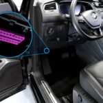
- OBD2 Connector (16 Pin Male): The interface that plugs into your car’s OBD2 port.
- 510 Ohm Resistor: Crucial for proper communication in some vehicle systems.
- Optional Combo Kit: Soldering Kit, Multimeter, and Cutter Combo can be a convenient option if you need multiple tools.
Step-by-Step Guide to Building Your OBD2 to Laptop Cable
Follow these steps carefully to construct your OBD2 cable. Accuracy in wiring is crucial for the cable to function correctly and avoid damaging your vehicle’s electronics.
1. Preparing the Ethernet Cable
Begin by cutting your Ethernet cable in half. This gives you two ends to work with, and for this project, you’ll only need one half. Slide a cable protector and boot onto the cut end of the Ethernet cable. These will provide strain relief and a professional finish to your DIY cable.
2. Exposing Ethernet Wires
Carefully remove the outer plastic jacket of the Ethernet cable to expose the internal wires. You’ll find eight wires, each with a different color code. Understanding this color code is vital for correct wiring. The standard Ethernet cable wiring (T568B) is depicted below, which is essential for identifying each pin.
Identify the color of the wire for each pin number as this is crucial for the next steps. Tin the exposed edges of each wire using your soldering iron. This preps the wires for easier soldering to the OBD2 connector. For this DIY OBD2 cable, pins 4, 5, and 7 of the Ethernet cable are not needed. You can cut off the Blue, White/Blue, and White/Brown wires to avoid confusion.
3. Opening the OBD2 Connector
Next, open up the OBD2 connector. You will see it has 16 pins, arranged in two rows of eight. These pins are numbered 1 to 16, which is usually indicated on the connector itself.
4. Testing the Resistor
Before soldering, it’s important to check your 510 Ohm resistor with a multimeter. Ensure the resistance is within the range of 506-560 Ohms. This step confirms the resistor is within the correct specification for the cable to function properly.
5. Soldering and Wiring
Refer to the pinout diagram below to understand which Ethernet cable wire needs to be soldered to which pin on the OBD2 connector. Accuracy here is paramount.
Follow this wiring scheme:
| Ethernet Pin | Wire Color | OBD2 Pin |
|---|---|---|
| Pin 1 | White/Orange | Pin 3 |
| Pin 2 | Orange | Pin 11 |
| Pin 3 | White/Green | Pin 12 |
| Pin 6 | Green | Pin 13 |
| Pin 8 | Brown | Pin 4 & 5 |
Finally, solder the 510 Ohm resistor to Pins 8 and 16 of the OBD2 connector. This resistor is essential for certain vehicle communication protocols and ensures compatibility.
Final Steps
After completing all the soldering, carefully close the OBD2 connector cover. Your DIY Obd2 Cable To Laptop cable is now ready! Connect it to your car’s OBD2 port and your laptop to start diagnostics, coding, or performance monitoring.
This DIY guide empowers you to create your own OBD2 cable, saving money and gaining a deeper understanding of automotive electronics. Remember to always double-check your connections and wiring diagrams to ensure safety and proper functionality when working with your vehicle’s systems.