Understanding the fuse box layout in your 2003 Ford F-150 is crucial for diagnosing and resolving electrical issues. Locating the correct fuse, especially for components like the OBD2 port, can save you time and prevent unnecessary repairs. This guide will provide you with detailed fuse box diagrams for the 2003 Ford F-150, focusing on identifying fuses relevant to the OBD2 system and other essential vehicle functions.
Your 2003 Ford F-150 is equipped with two primary fuse boxes. Knowing the location and function of each fuse within these boxes is essential for maintaining your vehicle’s electrical system. Below are diagrams and descriptions to help you navigate your fuse boxes effectively.
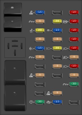
Passenger Compartment Fuse Box Diagram
The passenger compartment fuse panel in your 2003 Ford F-150 is situated inside the vehicle. This fuse box houses fuses and relays that control many of the interior and some of the engine management systems.
| Type | No. | Description |
|---|---|---|
| Fuse MINI 15A | 1 | Audio |
| Fuse MINI 5A | 2 | Powertrain Control Module (PCM), Cluster |
| Fuse MINI 20A | 3 | Cigar lighter, Data link connector |
| Fuse MINI 5A | 4 | Power mirror switch, Mirror turn signal relays |
| Fuse MINI 15A | 5 | Speed control module, Reverse lamp, Climate mode switch, Daytime Running Lamps (DRL) relay, Digital Transmission Range (DTR) sensor |
| Fuse MINI 5A | 6 | Cluster, Brake shift interlock solenoid, GEM |
| Fuse MINI 5A | 8 | Radio, Remote entry module, GEM, In-vehicle entertainment system (SuperCrew only) |
| Fuse MINI 30A | 11 | Front washer pump relay, Wiper run/park relay, Wiper HI/LO relay, Windshield wiper motor |
| Fuse MINI 20A | 13 | Stop lamp switch (Lamps), Turn/Hazard flasher |
| Fuse MINI 15A | 14 | Battery saver relay, Interior lamp relay |
| Fuse MINI 5A | 15 | Stop lamp switch (speed control, brake shift interlock), GEM, Rear Anti-lock Brake System (RABS) module |
| Fuse MINI 20A | 16 | Headlamps (hi beams), Cluster (hi beam indicator) |
| Fuse MINI 5A | 18 | Instrument illumination (dimmer switch power) |
| Fuse MINI 5A | 20 | Audio, GEM, PCM, Transmission range sensor |
| Fuse MINI 15A | 21 | DTR sensor, Clutch switch, Starter relay, I/P fuse 20 |
| Fuse MINI 10A | 22 | Air bag module, Passenger air bag deactivation module |
| Fuse MINI 10A | 23 | Trailer tow battery Charge relay, Turn/Hazard flasher, 4×4 solenoids, 4×4 relays, Overhead console, 4-Wheel Anti-lock Brake System (4WABS) module, EC mirror, Heated seats |
| Fuse MINI 10A | 24 | Function selector switch assembly |
| Fuse MINI 10A | 25 | Heated mirrors |
| Fuse MINI 10A | 26 | Right-hand low beam headlamp |
| Fuse MINI 5A | 27 | Foglamp relay and foglamp indicator, Main light switch (upstream) |
| Fuse MINI 10A | 28 | Left-hand low beam headlamp |
| Fuse MINI 5A | 29 | Autolamp module, Transmission overdrive control switch, Central security module, Beltminder |
| Fuse MINI 30A | 30 | Passive Anti-theft transceiver, Cluster, Ignition coils, PCM relay, Coil on plugs, Radio noise capacitor, ECC diode |
| Relay | R1 | Interior lamp relay |
| Relay | R2 | Battery saver relay |
| Relay | R4 | One-touch down window relay |
| Relay | R5 | Accessory delay relay |

Power Distribution Box Diagram
The power distribution box in the 2003 Ford F-150 is located under the hood, typically in the engine compartment. This box contains fuses and relays for high-current circuits and engine-related systems.
| Type | No. | Description |
|---|---|---|
| Fuse MINI 20A | 1 | Power point |
| Fuse MINI 30A | 2 | Powertrain Control Module (PCM) |
| Fuse MINI 30A | 3 | Main light switch, Headlamp relay, Multifunction switch |
| Fuse MINI 20A | 4 | Console power point [Harley Davidson only] |
| Fuse MINI 20A | 5 | Trailer tow back-up/park lamps |
| Fuse MINI 15A | 6 | Main light switch, Park lamp relay |
| Fuse MINI 20A | 7 | Horn |
| Fuse MINI 15A | 8 | Power door locks, Central Security Module (CSM), Lock relays [not used on SuperCrew] |
| Fuse MINI 15A | 9 | Daytime Running Lamps (DRL), Fog lamps |
| Fuse MINI 20A | 10 | Fuel pump |
| Fuse MINI 20A | 11 | Alternator field |
| Fuse MINI 20A | 12 | Rear auxiliary power point [SuperCrew only] |
| Fuse MINI 15A | 13 | A/C clutch |
| Fuse MINI 10A | 15 | Running board lamps |
| Fuse MINI 15A | 16 | Bi-fuel injector module, fuel selector switch and alternative fuel injectors [Bi-fuel vehicles only] |
| Fuse MINI 15A | 18 | PCM, Fuel injectors, Fuel pump relay, Mass air flow sensor |
| Fuse MINI 10A | 19 | Trailer/Camper adapter (right stop/turn lamp) |
| Fuse MINI 10A | 20 | Trailer/Camper adapter (left stop/turn lamp) |
| Fuse MINI 15A | 23 | HEGO sensor, Automatic transmission |
| Fuse FMX/JCase 30A | 101 | Trailer tow battery charge |
| Fuse FMX/JCase 20A | 102 | Four-wheel Anti-lock Brake System (4WABS) module/Rear-wheel Anti-lock Brake System (RABS) module, Ignition switch |
| Fuse FMX/JCase 50A | 103 | Central junction box |
| Fuse FMX/JCase 30A | 104 | 4×4 shift motor & clutch |
| Fuse FMX/JCase 40A | 105 | Climate control front blower |
| Fuse FMX/JCase 20A | 106 | Intercooler pump [supercharged engine only] |
| Fuse FMX/JCase 30A | 108 | Trailer tow electric brake |
| Fuse FMX/JCase 30A | 110 | Accessory delay relay [Not used on SuperCrew] |
| Fuse FMX/JCase 40A | 111 | Ignition switch battery feed (start and run circuits) |
| Fuse FMX/JCase 30A | 112 | Drivers power seat, Adjustable pedal switch |
| Fuse FMX/JCase 40A | 113 | Ignition switch battery feed (run and accessory circuits) |
| Fuse FMX/JCase 20A | 115 | Power door locks [SuperCrew only] |
| Fuse FMX/JCase 40A | 116 | Heated backlight |
| Fuse FMX/JCase 40A | 117 | Audiophile radio [SuperCrew only] |
| Fuse FMX/JCase 30A | 118 | Heated seats |
| Relay | 201 | Trailer tow park lamp relay |
| Relay | 202 | Front wiper run/park relay |
| Relay | 203 | Trailer tow backup lamp relay |
| Relay | 204 | A/C clutch relay |
| Relay | 205 | Horn relay |
| Relay | 206 | Fog lamp relay |
| Relay | 207 | Front washer pump relay |
| Relay | 208 | Intercooler pump relay [supercharged engine only] |
| Relay | 209 | Front wiper HI/LO relay |
| Relay | 301 | Fuel pump relay |
| Relay | 302 | Trailer tow battery charge relay |
| Relay | 303 | Heated backlight relay [SuperCrew only] |
| Relay | 304 | PCM relay |
| Relay | 305 | Fuel pump HI/LO relay [supercharged engine only] |
| Relay | 306 | Inertia switch relay [supercharged engine only] |
| Diode ATO | 501 | PCM diode |
| Diode ATO | 502 | A/C compressor diode |
| Circuit breaker MAXI | 601 | Power windows, Moonroof [SuperCrew only] |
Identifying the OBD2 Fuse
While there isn’t a fuse explicitly labeled “OBD2 fuse” in the 2003 Ford F-150 fuse box diagrams, the OBD2 port (Data Link Connector) is essential for diagnostics. The fuse that powers the OBD2 port is often linked to other systems. Based on the diagrams, here are the fuses to check if you are experiencing issues with your OBD2 port:
-
Passenger Compartment Fuse Box:
- Fuse #3 (20A): Cigar lighter, Data link connector. This fuse is the most likely candidate for powering your OBD2 port. If your cigarette lighter is also not working, this fuse is a prime suspect.
- Fuse #2 (5A): Powertrain Control Module (PCM), Cluster. The PCM is critical for vehicle diagnostics, and this fuse protects it along with the instrument cluster. A blown fuse here could affect OBD2 communication.
- Fuse #20 (5A): Audio, GEM, PCM, Transmission range sensor. This is another fuse linked to the PCM, and should be checked if you are having OBD2 issues, especially alongside problems with the audio system.
-
Power Distribution Box:
- Fuse #2 (30A): Powertrain Control Module (PCM). This high-amperage fuse in the engine compartment also protects the PCM. While less directly linked to the OBD2 port itself, a problem here could prevent the PCM from functioning correctly, thus impacting OBD2 communication.
Troubleshooting OBD2 Fuse Issues
If you suspect a blown fuse is causing issues with your OBD2 port, follow these steps:
- Locate the Fuse Boxes: Use the diagrams above to find the passenger compartment and power distribution fuse boxes in your 2003 Ford F-150.
- Identify Potential Fuses: Refer to the descriptions above to pinpoint fuses #3, #2, and #20 in the passenger compartment box, and fuse #2 in the power distribution box.
- Inspect the Fuses: Use a fuse puller (often found in the fuse box) or needle-nose pliers to carefully remove each fuse. Hold the fuse up to the light and check if the thin wire inside is broken or melted. A broken wire indicates a blown fuse.
- Replace the Fuse: If a fuse is blown, replace it with a new fuse of the exact same amperage. Do not use a higher amperage fuse, as this can damage your vehicle’s electrical system.
- Test the OBD2 Port: After replacing the fuse, try using your OBD2 scanner again to see if the issue is resolved.
Important Notes:
- Always consult your 2003 Ford F-150 owner’s manual for the most accurate fuse information and locations, as there might be slight variations.
- If you frequently blow fuses, it indicates a larger electrical problem that needs professional diagnosis. Consult a qualified mechanic to identify and repair the underlying issue.
- Never replace a fuse with one of a higher amperage rating. This can lead to serious electrical damage and even fire.
By understanding your 2003 Ford F-150 fuse box diagrams and knowing which fuses are related to the OBD2 system, you can effectively troubleshoot common electrical problems and maintain your vehicle’s diagnostic capabilities.