Since 1996, OBD-II compliance has been a standard for all cars and light trucks sold in the United States, ensuring vehicles are equipped for standardized diagnostics. European OBD legislation follows a similar but nuanced approach. This standardization allows for consistent vehicle communication using a set of protocols. Understanding these OBD2 protocols is crucial for effective vehicle diagnostics and repair.
OBD-II systems utilize five primary communication protocols: J1850 PWM, J1850 VPW, ISO9141-2, ISO14230-4 (Keyword Protocol 2000), and the more modern ISO15765-4/SAE J2480 (CAN protocol). Initially, US manufacturers were restricted from using the CAN protocol until the 2003 model year. However, since 2008, CAN protocol has become mandatory for all vehicles. Identifying the specific protocol your vehicle uses is the first step in effective OBD2 diagnostics.
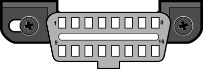
Diagnostic Link Connectors (DLCs), as defined by SAE J1962, come in two types: Type A and Type B. These connectors are the physical interface points for diagnostic tools to communicate with your vehicle’s computer. The primary difference between Type A and Type B connectors lies in the alignment tab shape, ensuring correct connection.
Fig. 1 – J1962 Vehicle Connector, Type A
Type A DLCs are typically located within the driver or passenger compartment, spanning from the driver’s side of the instrument panel to approximately one foot beyond the vehicle’s center line. Optimal placement is often between the steering column and the vehicle’s center. This location prioritizes accessibility for the driver.
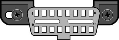
Type B DLCs offer more flexible placement options. They can be found in the passenger or driver’s compartment, extending from the driver’s instrument panel, including the outer side, to about 2.5 feet beyond the vehicle centerline. These connectors are designed for easy access from the driver’s seat, co-driver’s seat, or even from outside the vehicle, facilitating easier diagnostic access in various situations.
Fig. 2 – J1962 Vehicle Connector, Type B
Determining your vehicle’s OBD2 protocol often involves examining the DLC pinout. By inspecting which pins are populated in the 16-pin connector, you can often deduce the communication protocol in use.
Fig. 3 – J1962F OBDII connector pinout
The table below outlines how to identify the protocol based on pin presence:
| Pin 2 | Pin 6 | Pin 7 | Pin 10 | Pin 14 | Pin 15 | Protocol |
|---|---|---|---|---|---|---|
| Must have | – | – | Must have | – | – | J1850 PWM |
| Must have | – | – | – | – | – | J1850 VPW |
| – | – | Must have | – | – | May have* | ISO9141/14230 |
| – | Must have | – | – | Must have | – | ISO15765 (CAN) |
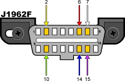
*Pin 15 (L-line) is optional in newer vehicles using ISO9141-2 or ISO14230-4 protocols.
Essential pins for OBD2 compliance include pins 4 (Chassis Ground), 5 (Signal Ground), and 16 (Battery Positive), which should always be present in the DLC. Based on the protocol:
PWM Protocol Requires pins 2, 4, 5, 10, and 16. VPW Protocol Requires pins 2, 4, 5, and 16, but not pin 10. ISO Protocol Requires pins 4, 5, 7, and 16. Pin 15 may or may not be present. CAN Protocol Requires pins 4, 5, 6, 14, and 16.
While pinout analysis offers a general guide to OBD2 protocols, for more detailed information specific to vehicle manufacturers, resources like OBDII Generic Communication Protocols by Manufacturer can be helpful in understanding protocol implementation across different makes and models. Understanding these protocols is a fundamental step in effective automotive diagnostics and repair.