The On-Board Diagnostics II (OBD2) system is a cornerstone of modern vehicle maintenance and diagnostics. At the heart of this system lies the standardized 16 Pin Obd2 Connector, a seemingly simple interface that unlocks a wealth of data about your vehicle’s health and performance. This guide provides an in-depth look at the 16 pin OBD2 connector, its function, and its critical role in accessing your car’s diagnostic information.
You’ve likely encountered the OBD2 system without even realizing it. That check engine light illuminating on your dashboard? That’s the OBD2 system signaling a potential issue. When you take your car to a mechanic, the first thing they often do is plug an OBD2 scanner into a port usually located near the steering wheel. This port is the 16 pin OBD2 connector, and it serves as the gateway to your vehicle’s self-diagnostic system. Through this connector, mechanics and car enthusiasts alike can request and receive real-time data, diagnostic trouble codes (DTCs), and much more, enabling efficient troubleshooting and vehicle monitoring.
Alt text: Malfunction Indicator Light (MIL) or Check Engine Light on a car dashboard, indicating an OBD2 system alert.
Does Your Car Have a 16 Pin OBD2 Connector?
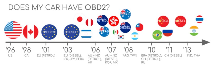
The answer is almost certainly yes, especially if you own a non-electric car manufactured in recent decades. The standardization of OBD2 and the 16 pin OBD2 connector is widespread across the automotive industry. However, it’s important to note that the presence of a 16 pin connector doesn’t automatically guarantee OBD2 compliance, particularly in older vehicles. A key indicator of OBD2 compliance is the vehicle’s origin and year of purchase:
Alt text: Timeline infographic showing OBD2 compliance mandates in the US and EU based on vehicle type and year.
A Brief History of OBD2 and the 16 Pin Connector
The story of OBD2 begins in California, driven by the California Air Resources Board (CARB). In the early 1990s, CARB mandated OBD systems for emission control in all new vehicles sold in California, starting from 1991. This initial OBD standard paved the way for OBD2.
The Society of Automotive Engineers (SAE) played a crucial role in developing the OBD2 standard. They standardized diagnostic trouble codes (DTCs) and, importantly for our focus, the 16 pin OBD2 connector. This standardization effort culminated in SAE J1962, the standard that defines the physical 16 pin OBD2 connector and its pinout.
The adoption of OBD2 was phased in globally:
- 1996: OBD2 became mandatory in the USA for cars and light trucks.
- 2001: The European Union mandated OBD2 for gasoline cars.
- 2003: The EU extended the mandate to include diesel cars (EOBD).
- 2005: OBD2 was required in the US for medium-duty vehicles.
- 2008: US vehicles were required to use ISO 15765-4 (CAN bus) as the foundation for OBD2 communication.
- 2010: OBD2 became mandatory for heavy-duty vehicles in the US.
Alt text: Graphic illustrating the historical development of OBD2, emphasizing emission control and data access via CAN bus.
Alt text: Timeline infographic summarizing key milestones in OBD2 history from its origins to widespread adoption.
Alt text: Conceptual image of OBD3 and future trends in vehicle diagnostics, including remote diagnostics and IoT integration.
The Future of OBD2 and the 16 Pin Connector
While the 16 pin OBD2 connector and the OBD2 standard have been incredibly successful, the automotive landscape is evolving. Electric vehicles (EVs), for instance, are not legally obligated to support OBD2 in the same way as internal combustion engine vehicles. Many modern EVs are moving away from standard OBD2 requests, opting for OEM-specific UDS communication protocols. This shift can make accessing diagnostic data from EVs more challenging, often requiring reverse engineering efforts.
However, for traditional vehicles, OBD2 and the 16 pin OBD2 connector are expected to remain relevant for the foreseeable future. Efforts are underway to enhance OBD communication, such as WWH-OBD (World Wide Harmonized OBD) and OBDonUDS (OBD on UDS). These initiatives aim to modernize OBD by utilizing the UDS protocol as a foundation, improving data richness and communication efficiency.
The concept of OBD3 envisions integrating telematics into all vehicles. This could involve adding a radio transponder to vehicles, allowing for wireless transmission of vehicle identification numbers (VIN) and DTCs for remote diagnostics and emission testing. While this could streamline processes, it also raises privacy concerns.
There’s also ongoing debate within the automotive industry regarding third-party access to vehicle data via the OBD2 interface. Some manufacturers are exploring ways to limit this access, potentially centralizing data collection and control. This could impact the aftermarket OBD2 service and device industry.
Alt text: Visual metaphor depicting an OBD2 connector being removed from an electric vehicle, symbolizing restricted data access.
Delve Deeper into CAN Bus
Want to master CAN bus technology?
Our comprehensive ‘Ultimate CAN Guide’ provides 12 detailed introductions in a single, 160+ page PDF resource.
Download now
OBD2 Standards and the 16 Pin Connector
OBD2 operates as a higher-layer protocol, similar to a language, while CAN bus is the communication method, akin to a telephone line. This places OBD2 alongside other CAN-based protocols like J1939, CANopen, and NMEA 2000.
The OBD2 standards encompass various aspects, including the 16 pin OBD2 connector, lower-layer communication protocols, and OBD2 parameter IDs (PIDs). These standards are often categorized using the 7-layer OSI model, with both SAE (US standards) and ISO (international standards) contributing. Notably, SAE J1979 and ISO 15031-5 are technically equivalent standards for OBD diagnostics, and similarly, SAE J1962 and ISO 15031-3 both define the 16 pin OBD2 connector.
Alt text: OSI 7-layer model diagram illustrating the relationship between OBD2 and CAN bus protocols, highlighting relevant ISO and SAE standards.
Alt text: Diagram of an OBD2 connector pinout, Type A female socket, also known as Data Link Connector (DLC).
SAE J1962: Defining the 16 Pin OBD2 Connector
The 16-pin OBD2 connector, standardized under SAE J1962 and ISO 15031-3, is your primary physical access point to your vehicle’s diagnostic data. It’s commonly referred to as the Data Link Connector (DLC). Here are key features of the 16 pin OBD2 connector:
- Location: Typically found within reach of the driver’s seat, often under the dashboard near the steering column, though its exact location can vary and may sometimes be hidden behind a panel.
- Pin 16: Always provides battery power, even when the ignition is off, which is crucial for scanners and data loggers to operate.
- Pinout Variability: The specific function of other pins in the 16 pin OBD2 connector depends on the communication protocol used by the vehicle.
- CAN Bus Connection: In modern vehicles using CAN bus for OBD2, pins 6 (CAN High) and 14 (CAN Low) are essential for communication.
Type A vs. Type B 16 Pin OBD2 Connectors
While most cars utilize the Type A 16 pin OBD2 connector, Type B connectors are also encountered, particularly in medium and heavy-duty vehicles. Both types adhere to the 16-pin configuration but differ in power supply and sometimes communication speeds.
- Type A: Commonly found in cars, typically provides 12V power.
- Type B: Prevalent in trucks and heavy-duty vehicles, usually supplies 24V power. Often uses a slower 250K baud rate CAN bus compared to the 500K baud rate common in cars (though 500K is increasingly supported in heavy-duty vehicles).
Visually, Type B 16 pin OBD2 connectors are distinguished by an interrupted groove in the center, unlike the continuous groove of Type A. Type B OBD2 adapter cables are often designed to be compatible with both Type A and Type B sockets, whereas Type A adapters may not fit into Type B sockets.
Alt text: Illustration comparing OBD2 Connector Type A and Type B, highlighting voltage differences (12V vs 24V) and application in cars vs. trucks.
Alt text: Diagram illustrating the relationship between OBD2 and CAN bus according to ISO 15765 standards.
OBD2 Communication over CAN Bus (ISO 15765-4) and the 16 Pin Connector
Since 2008, CAN bus has been the mandated lower-layer protocol for OBD2 in US vehicles, as defined by ISO 15765. ISO 15765-4, also known as Diagnostics over CAN (DoCAN), specifies how OBD2 communication is implemented over CAN bus, focusing on the physical, data link, and network layers. The 16 pin OBD2 connector provides the physical interface for this communication.
Key aspects of ISO 15765-4 include:
- CAN Bus Bit-rate: Must be either 250K or 500K.
- CAN IDs: Supports both 11-bit and 29-bit CAN identifiers.
- OBD2 Specific CAN IDs: Standardized CAN IDs are used for OBD requests and responses.
- Data Length: Diagnostic CAN frames are limited to 8 bytes of data.
- Cable Length: OBD2 adapter cables should not exceed 5 meters in length.
OBD2 CAN Identifiers and the 16 Pin Connector
OBD2 communication is based on a request-response model. Using the 16 pin OBD2 connector and appropriate tools, external devices can send requests and receive responses.
In most cars, 11-bit CAN IDs are used for OBD2 communication. The ‘Functional Addressing’ ID, 0x7DF, is used to broadcast requests to all OBD2-compliant Electronic Control Units (ECUs) in the vehicle. ‘Physical Addressing’ requests, targeting specific ECUs, can be sent using CAN IDs 0x7E0-0x7E7, though these are less common.
ECUs respond with 11-bit IDs in the range 0x7E8-0x7EF. The most frequent response ID is 0x7E8, typically originating from the Engine Control Module (ECM), followed by 0x7E9 from the Transmission Control Module (TCM).
Some vehicles, particularly vans and medium/heavy-duty vehicles, may utilize 29-bit extended CAN identifiers for OBD2 communication. In these cases, the ‘Functional Addressing’ CAN ID is 0x18DB33F1. Responses are typically in the range 0x18DAF100 to 0x18DAF1FF, with common IDs like 0x18DAF110 and 0x18DAF11E. These 29-bit IDs are sometimes represented as J1939 Parameter Group Numbers (PGNs), specifically PGN 0xDA00 (55808), which is reserved for ISO 15765-2 in the J1939-71 standard.
Alt text: Diagram illustrating OBD2 request and response frames, showing PID data and parameters within the frame structure.
Alt text: Conceptual image contrasting OBD2 standard CAN bus data with proprietary OEM-specific CAN bus data.
OBD2 vs. OEM-Specific CAN Protocols and the 16 Pin Connector
It’s crucial to understand that while the 16 pin OBD2 connector provides access to OBD2 data, vehicle ECUs primarily operate using OEM-specific CAN protocols. These proprietary protocols are designed by the vehicle manufacturer and are often unique to specific brands, models, and years. Unless you possess OEM-specific knowledge or engage in reverse engineering, interpreting this raw CAN data is typically not possible.
When you connect a CAN bus data logger to the 16 pin OBD2 connector, you might observe OEM-specific CAN data alongside OBD2 communication. However, in many newer vehicles, a gateway module may restrict access to this OEM data through the OBD2 port, allowing only standardized OBD2 communication.
Think of OBD2 as an additional, standardized layer of communication that coexists with the OEM’s proprietary communication network, both accessible through the 16 pin OBD2 connector, although access to the OEM data may be limited.
Bit-rate and ID Validation for OBD2 via the 16 Pin Connector
As OBD2 over CAN bus can utilize two bit-rates (250K, 500K) and two CAN ID lengths (11-bit, 29-bit), there are four potential protocol combinations. Modern cars commonly use 500K and 11-bit IDs, but robust OBD2 tools should systematically validate these parameters. ISO 15765-4 outlines a procedure for automatic protocol detection, which involves sending a mandatory OBD2 request and checking for a valid response. Incorrect bit-rate settings will result in CAN error frames, signaling a mismatch.
Newer versions of ISO 15765-4 also consider OBDonUDS (OBD on Unified Diagnostic Services) as an alternative to the more common OBDonEDS (OBD on Emission Diagnostic Service). While this article primarily focuses on OBDonEDS (also known as OBD2, SAE OBD, EOBD, or ISO OBD), OBDonUDS is gaining traction, particularly in EU trucks and buses (WWH-OBD). To differentiate between these protocols, advanced tools may send UDS requests to specific service and data identifier addresses (like service 0x22 and DID 0xF810) to check for OBDonUDS support.
Alt text: Flowchart illustrating the OBD2 bit-rate and CAN ID validation process as per ISO 15765-4 standards.
Alt text: Graphic depicting the five lower-layer OBD2 protocols: CAN (ISO 15765), KWP2000 (ISO14230-4), ISO 9141-2, SAE J1850 VPW, and SAE J1850 PWM.
Legacy OBD2 Protocols and the 16 Pin Connector
While CAN bus (ISO 15765) dominates modern OBD2 communication via the 16 pin OBD2 connector, older vehicles (pre-2008) may utilize one of four other lower-layer protocols. Understanding these protocols and their pin assignments within the 16 pin OBD2 connector can be helpful when working with older cars:
- ISO 15765 (CAN bus): Mandatory in US cars since 2008 and now the most prevalent.
- ISO14230-4 (KWP2000): Keyword Protocol 2000, common in 2003+ vehicles, especially in Asia.
- ISO 9141-2: Used in European, Chrysler, and Asian vehicles from approximately 2000-2004.
- SAE J1850 (VPW): Variable Pulse Width Modulation, primarily used in older General Motors (GM) vehicles.
- SAE J1850 (PWM): Pulse Width Modulation, mainly used in older Ford vehicles.
ISO-TP (ISO 15765-2) and Multi-Frame OBD2 Messages via the 16 Pin Connector
All OBD2 data transmitted through the 16 pin OBD2 connector over CAN bus utilizes the ISO-TP (ISO 15765-2) transport protocol. ISO-TP enables the transmission of data payloads exceeding the 8-byte limit of standard CAN frames. This is essential for OBD2 functions like retrieving the Vehicle Identification Number (VIN) or Diagnostic Trouble Codes (DTCs), which often require more than 8 bytes of data. ISO-TP handles segmentation, flow control, and reassembly of these larger messages.
For simpler OBD2 requests and responses where the data fits within a single CAN frame, ISO 15765-2 specifies the use of ‘Single Frame’ (SF) messages. In a Single Frame, the first data byte (PCI field) indicates the payload length, leaving 7 bytes for OBD2-specific data.
Alt text: Diagram illustrating ISO 15765-2 ISO-TP frame types used in OBD2 communication, including Single Frame, First Frame, Consecutive Frame, and Flow Control Frame.
Decoding OBD2 Diagnostic Messages from the 16 Pin Connector (SAE J1979, ISO 15031-5)
To understand OBD2 communication at a message level, consider a ‘Single Frame’ OBD2 CAN message transmitted and received via the 16 pin OBD2 connector. A simplified OBD2 message structure includes a CAN identifier, data length (PCI field), and the data payload. The payload itself is structured into Mode, Parameter ID (PID), and data bytes.
Alt text: Breakdown of an OBD2 message structure, explaining the components: Mode, PID, Identifier, and Data Bytes.
OBD2 Request/Response Example via the 16 Pin Connector
Let’s examine an example of requesting ‘Vehicle Speed’ using OBD2 through the 16 pin OBD2 connector.
An external tool sends a request message via the 16 pin OBD2 connector with CAN ID 0x7DF and a 2-byte payload: Mode 0x01 (Show current data) and PID 0x0D (Vehicle Speed). The vehicle responds through the 16 pin OBD2 connector with CAN ID 0x7E8 and a 3-byte payload. The vehicle speed value is encoded in the 4th byte of the CAN data frame, in this case, 0x32 (decimal 50). Using OBD2 PID decoding rules, 0x32 corresponds to 50 km/h.
Alt text: Example of an OBD2 request and response sequence for Vehicle Speed, showing CAN IDs 7DF (request) and 7E8 (response).
Alt text: Detailed example of OBD2 PID 0x0D (Vehicle Speed), illustrating the request and response data and decoding process.
Alt text: Graphic outlining the 10 OBD2 service modes or diagnostic services, including current data, freeze frame, and DTC clearing.
The 10 OBD2 Services (Modes) Accessed via the 16 Pin Connector
OBD2 defines 10 diagnostic services, often referred to as modes, accessible via the 16 pin OBD2 connector. Mode 0x01 is used to retrieve real-time data, while other modes are designed for accessing and clearing diagnostic trouble codes (DTCs) or retrieving freeze frame data.
It’s important to note that vehicles are not required to support all 10 OBD2 modes, and manufacturers may implement additional OEM-specific modes beyond the standard set. In OBD2 messages, the mode is indicated in the second byte of the payload. In a request message, the mode is included directly (e.g., 0x01). In a response message, 0x40 is added to the requested mode (e.g., a response to mode 0x01 will have mode 0x41).
OBD2 Parameter IDs (PIDs) and the 16 Pin Connector
Within each OBD2 mode, there are Parameter IDs (PIDs). For example, mode 0x01 encompasses approximately 200 standardized PIDs providing real-time data on parameters like speed, RPM, and fuel level. However, vehicles typically support only a subset of the available PIDs within each mode.
A crucial PID for compatibility testing is PID 0x00 in mode 0x01. If an ECU supports any OBD2 services, it must support mode 0x01 PID 0x00. Responding to this PID, the ECU indicates its support for PIDs 0x01-0x20. This makes PID 0x00 a fundamental test for OBD2 compliance through the 16 pin OBD2 connector. Similarly, PIDs 0x20, 0x40, and so on, up to 0xC0, can be used to check support for subsequent PID ranges in mode 0x01.
Alt text: Diagram again illustrating OBD2 request and response frames, emphasizing the role of PIDs in requesting specific data parameters.
Alt text: Screenshot of an OBD2 PID overview tool, showing Service 01 and available PIDs for data retrieval.
OBD2 PID Overview Tools
SAE J1979 and ISO 15031-5 appendices detail the scaling and decoding information for standard OBD2 PIDs, enabling conversion of raw data into physical values. For quick lookups of mode 0x01 PIDs, online OBD2 PID overview tools are invaluable. These tools assist in constructing OBD2 request frames and dynamically decoding responses received via the 16 pin OBD2 connector.
OBD2 PID overview tool
Practical OBD2 Data Logging and Decoding via the 16 Pin Connector
Let’s explore a practical example of logging OBD2 data using a CANedge CAN bus data logger connected through the 16 pin OBD2 connector. The CANedge allows configuration of custom CAN frames for transmission, enabling OBD2 request sending and data logging. Connecting the CANedge to your vehicle is straightforward using an OBD2-DB9 adapter cable.
Alt text: Diagram showing an OBD2 data logger setup, requesting PIDs via CAN IDs 7DF and 7E8.
Alt text: Screenshot showing a bit-rate validation test for OBD2 communication, confirming successful CAN frame transmission.
Alt text: Screenshot from asammdf software displaying OBD2 PID test responses, used to review supported PIDs.
Step #1: Bit-rate, ID, and Supported PID Testing via the 16 Pin Connector
As per ISO 15765-4, the initial step involves determining the correct bit-rate and CAN IDs for your vehicle’s OBD2 communication through the 16 pin OBD2 connector. This can be done using a CANedge or similar tool:
- Bit-rate Test: Send a CAN frame at 500K baud. If successful, use 500K; otherwise, try 250K.
- Protocol Validation: Use the identified bit-rate for subsequent communication.
- Supported PID Discovery: Send ‘Supported PIDs’ requests (Mode 0x01 PID 0x00 and subsequent range PIDs) and analyze the responses.
- CAN ID Determination: Based on response IDs, determine if 11-bit or 29-bit CAN IDs are used.
- Supported PID Identification: Analyze response data to identify the PIDs supported by the vehicle.
Pre-configured CANedge configurations are available to streamline these tests. Most post-2008 non-EV cars typically support 40-80 PIDs using 500K bit-rate, 11-bit CAN IDs, and the OB