Understanding your 2007 Ford F-150’s fuse box is crucial for diagnosing and resolving electrical issues. Fuses protect your truck’s electrical circuits from overloads, and knowing their locations and functions can save you time and money on repairs. While there isn’t a fuse specifically labeled “OBD2 fuse,” the fuse that powers your OBD2 diagnostic port is vital for vehicle scanning and diagnostics. This article will guide you through the fuse box locations, diagrams, and fuse descriptions for your 2007 Ford F-150, ensuring you can quickly identify and address any fuse-related problems, including those affecting your OBD2 port’s functionality.
Your 2007 Ford F-150 is equipped with three different fuse boxes, each serving specific circuits in your vehicle’s electrical system. Locating the right fuse box and understanding its diagram is the first step in troubleshooting electrical problems.
Fuse Box Locations and Diagrams
-
Passenger Compartment Fuse Panel / Power Distribution Box
This fuse box is located inside the cabin of your F-150, typically beneath the dashboard on the passenger side. It is often referred to as the central fuse box and controls many interior and some exterior functions.
The diagram above illustrates the layout of the passenger compartment fuse panel. Below is a detailed table outlining each fuse and relay within this box, along with its amperage and the circuits it protects. Notably, Fuse #41, a 20A fuse, is responsible for the “Diagnostic connector power,” which powers your OBD2 port. If you’re experiencing issues connecting your scan tool, this fuse should be one of the first you check.
Type No. Description Fuse MINI 10A 1 Run/Accessory – Wipers, Instrument cluster, Audio for XL/STX Fuse MINI 20A 2 Stop/Turn lamps, Brake on/off switch, Hazard flashers Fuse MINI 7.5A 3 Power mirrors, Memory seats and pedals, Driver power seat Fuse MINI 10A 4 DVD battery power, Power fold mirror Fuse MINI 7.5A 5 Keep alive memory for Powertrain Control Module (PCM) and climate control module Fuse MINI 15A 6 Parklamps, BSM, Instrument panel illumination Fuse MINI 5A 7 Radio (start signal) Fuse MINI 10A 8 Heated mirrors, Switch indicator Fuse MINI 20A 9 Fuel pump relay, Fuel injectors, Intake manifold runner control [4.2L] Fuse MINI 20A 10 Trailer tow back-up lamps relay (PCB1), Trailer tow parklamp relay (R201) Fuse MINI 10A 11 A/C clutch, 4×4 solenoid Fuse MINI 5A 12 PCM relay coil Fuse MINI 10A 13 Climate control module power, Flasher relay Fuse MINI 10A 14 Back-up lamp and Daytime Running Lamps (DRL) relay coil, A/C pressure switch, Redundant speed control switch, Heated PCV [5.4L], Trailer tow back-up lamps relay coil, ABS, Reverse park aid, EC mirror, Navigation radio (reverse input) Fuse MINI 5A 15 Overdrive cancel, Cluster, Traction control switch Fuse MINI 10A 16 Brake-shift interlock solenoid Fuse MINI 15A 17 Fog lamp relay (R202) Fuse MINI 10A 18 Run/Start feed – Overhead power point, Electrochromatic mirror, Heated seats, BSM, Compass, RSS (Reverse Sensing System) Fuse MINI 10A 19 Restraints (Air bag module), OCS Fuse MINI 10A 20 Battery feed for overhead power point Fuse MINI 15A 21 Cluster keep alive power Fuse MINI 10A 22 Delayed accessory power for audio, power door lock switch and moon roof switch illumination Fuse MINI 10A 23 RH low beam headlamp Fuse MINI 15A 24 Battery saver power for demand lamps Fuse MINI 10A 25 LH low beam headlamp Fuse MINI 20A 26 Horn relay (PCB3), Horn power Fuse MINI 5A 27 Passenger Air bag Deactivation (PAD) warning lamp, Cluster RUN /START power Fuse MINI 5A 28 SecuriLock transceiver (PATS), PCM IGN monitor Fuse MINI 15A 29 PCM 4×4 power Fuse MINI 15A 30 PCM 4×4 power Fuse MINI 20A 31 Radio power, Satellite radio module Fuse MINI 15A 32 Vapor Management Valve (VMV), A/C clutch relay, Canister vent, Heated Exhaust Gas Oxygen (HEGO) sensors #11 and #21, CMCV, Mass Air Flow (MAF) sensor, VCT, Heated Positive Crankcase Ventilation (PCV) valve [4.2L engine], CID sensor [4.2L engine, 4.6L/4.2L EGR] , Electronic fan clutch [4.6L/5.4L engines] Fuse MINI 15A 33 Shift solenoid, CMS #12 and #22, Ignition coils Fuse MINI 15A 34 PCM power Fuse MINI 20A 35 Instrument cluster high beam indicator, High beam headlamps Fuse MINI 10A 36 Trailer tow right turn/stop lamps Fuse MINI 20A 37 Rear power point, Center console power point Fuse MINI 25A 38 Subwoofer power Fuse MINI 20A 39 Instrument panel power point Fuse MINI 20A 40 Low beam headlamps, DRL Fuse MINI 20A 41 Cigar lighter, Diagnostic connector power Fuse MINI 10A 42 Trailer tow left turn/stop lamps Fuse FMX/JCase 30A 101 Starter solenoid Fuse FMX/JCase 20A 102 Ignition switch feed Fuse FMX/JCase 20A 103 ABS valves Fuse FMX/JCase 30A 105 Electric trailer brakes Fuse FMX/JCase 30A 106 Trailer tow battery charge Fuse FMX/JCase 30A 107 Power door locks (BSM) Fuse FMX/JCase 30A 108 Passenger power seat Fuse FMX/JCase 30A 109 Driver power seat, Adjustable pedals, Memory module (pedals, seat, mirror) Fuse FMX/JCase 30A 111 4×4 relays Fuse FMX/JCase 40A 112 ABS pump power Fuse FMX/JCase 30A 113 Wipers and washer pump Fuse FMX/JCase 40A 114 Heated backlite, Heated mirror power Fuse FMX/JCase 20A 115 Not used (Spare) Fuse FMX/JCase 30A 116 Blower motor Fuse FMX/JCase 30A 118 Heated seats Circuit breaker MAXI 401 Delayed accessory power: Power windows, Moon roof, Power sliding backlite (circuit breaker) Relay R01 Starter solenoid Relay R02 Accessory delay Relay R03 Hi-beam headlamps Relay R04 Heated backlite Relay R05 Trailer tow battery charge Relay R06 Blower motor Relay R201 Trailer tow park lamps Relay R202 Fog lamps Relay R203 PCM 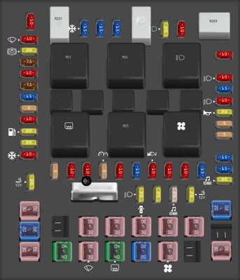
-
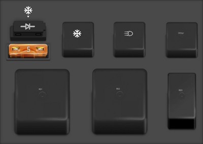
Auxiliary Relay Box (with DRL)
Some 2007 F-150 models, especially those equipped with Daytime Running Lights (DRL), have an auxiliary relay box. This box is typically located in the engine compartment.
The diagram for the auxiliary relay box (with DRL) is shown above. Here is the corresponding table detailing the fuses, relays, and diodes within this auxiliary box.
Type No. Description Fuse ATO 5A F03 Clockspring illumination Relay R01 4×4 CCW Relay R02 4×4 CW Relay R03 Daytime Running Lamps (DRL) high beam disable Relay R201 (DRL) Daytime running lights Relay R202 (A/C clutch) A/C magnetic clutch Diode ATO D01 (A/C clutch) A/C magnetic clutch -
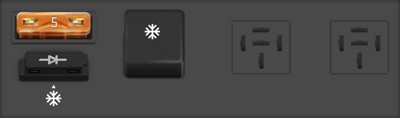
Auxiliary Relay Box (without DRL)
For 2007 F-150 models without Daytime Running Lights, the auxiliary relay box configuration is slightly different. This is also located in the engine compartment.
The diagram for the auxiliary relay box (without DRL) is presented above, and the table below provides details on its components.
Type No. Description Fuse ATO 5A F03 Clockspring illumination Diode ATO D01 A/C clutch Relay R202 A/C clutch
Understanding and Troubleshooting Fuses
Fuses are designed to break the circuit when excessive current flows through them, protecting components from damage. When diagnosing electrical issues in your 2007 Ford F-150, checking the fuses is a straightforward first step.
- Identifying a Blown Fuse: A blown fuse typically has a broken wire inside its clear plastic housing. Sometimes, it might be visually difficult to detect, so using a fuse tester or multimeter is recommended for accurate diagnosis.
- Checking Fuses: You can use a simple fuse tester or a multimeter to check for continuity. If there’s no continuity, the fuse is blown and needs replacement.
- Replacing Fuses: Always replace a blown fuse with one of the same amperage rating. Using a fuse with a higher rating can overload the circuit and cause further damage or even a fire.
- OBD2 Port Fuse Issues: If your OBD2 scanner is not powering up or connecting to your F-150, check Fuse #41 (20A) in the passenger compartment fuse panel. This fuse powers the diagnostic connector, and a blown fuse here will prevent communication with your vehicle’s computer.
By using these diagrams and fuse descriptions, you can effectively troubleshoot electrical problems in your 2007 Ford F-150. Remember to always consult your owner’s manual for the most accurate and up-to-date information specific to your vehicle.