Diagnosing issues with your 2007 Ford F-150 often starts with the On-Board Diagnostics II (OBD2) port. This crucial port allows mechanics and DIY enthusiasts to read trouble codes and understand what’s going on under the hood. However, if your OBD2 port isn’t working, a blown fuse might be the culprit. Locating the correct fuse is the first step to getting your diagnostics back online. This guide will walk you through finding the OBD2 fuse location and understanding the fuse box layout in your 2007 Ford F-150.
Understanding your 2007 Ford F-150’s fuse boxes is essential for basic maintenance and troubleshooting electrical problems. Unlike some vehicles with a single fuse box, the 2007 F-150 is equipped with three distinct fuse box locations. Knowing where each is and what it controls can save you time and frustration when dealing with electrical malfunctions, including issues related to your OBD2 port.
Decoding the Fuse Box Locations on Your 2007 F-150
Your 2007 Ford F-150 utilizes a system of three fuse boxes to manage its electrical circuits. These are strategically placed for accessibility and functional organization:
-
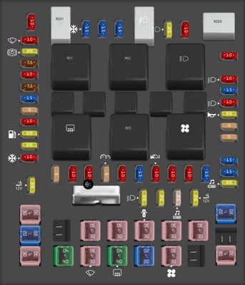
Passenger Compartment Fuse Panel: This fuse box is arguably the most frequently accessed, as it’s located inside the cabin. You can find it beneath the right side of the instrument panel. This panel houses fuses and relays that control many interior functions and some critical engine management systems.
-
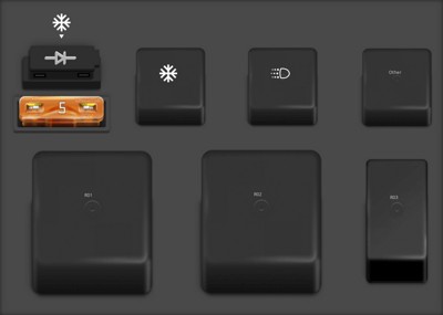
Auxiliary Relay Box (with DRL): Depending on whether your F-150 is equipped with Daytime Running Lights (DRL), you may have one of two auxiliary relay boxes. The version with DRL is located in the engine compartment, on the left-hand side.
-
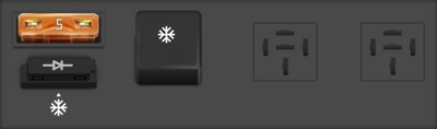
Auxiliary Relay Box (without DRL): For 2007 F-150 models without Daytime Running Lights, a slightly different auxiliary relay box is used. This is also situated in the engine compartment on the left-hand side, but has a different configuration reflecting the absence of DRL circuitry.
To help you visually identify these locations and their layouts, refer to the diagrams below:
Passenger compartment fuse panel diagram in a 2007 Ford F-150, highlighting its role as a power distribution box.
Diagram of the auxiliary relay box with DRL in a 2007 Ford F-150, showing component layout.
Auxiliary relay box diagram without DRL in a 2007 Ford F-150, illustrating the fuse and relay arrangement.
Pinpointing the OBD2 Fuse
For your OBD2 port, you’ll primarily be concerned with the Passenger Compartment Fuse Panel. Within this panel, fuse #41, a 20A Mini fuse, is designated for “Cigar lighter, Diagnostic connector power”. This fuse is the most likely culprit if your OBD2 port is not receiving power.
Below is a detailed fuse listing for the Passenger Compartment Fuse Panel. Locate fuse #41 to check if it’s blown. Remember to always replace a blown fuse with one of the same amperage to prevent further electrical issues.
| Type | No. | Description |
|---|---|---|
| Fuse MINI 10A | 1 | Run/Accessory – Wipers, Instrument cluster, Audio for XL/STX |
| Fuse MINI 20A | 2 | Stop/Turn lamps, Brake on/off switch, Hazard flashers |
| Fuse MINI 7.5A | 3 | Power mirrors, Memory seats and pedals, Driver power seat |
| Fuse MINI 10A | 4 | DVD battery power, Power fold mirror |
| Fuse MINI 7.5A | 5 | Keep alive memory for Powertrain Control Module (PCM) and climate control module |
| Fuse MINI 15A | 6 | Parklamps, BSM, Instrument panel illumination |
| Fuse MINI 5A | 7 | Radio (start signal) |
| Fuse MINI 10A | 8 | Heated mirrors, Switch indicator |
| Fuse MINI 20A | 9 | Fuel pump relay, Fuel injectors, Intake manifold runner control [4.2L] |
| Fuse MINI 20A | 10 | Trailer tow back-up lamps relay (PCB1), Trailer tow parklamp relay (R201) |
| Fuse MINI 10A | 11 | A/C clutch, 4×4 solenoid |
| Fuse MINI 5A | 12 | PCM relay coil |
| Fuse MINI 10A | 13 | Climate control module power, Flasher relay |
| Fuse MINI 10A | 14 | Back-up lamp and Daytime Running Lamps (DRL) relay coil, A/C pressure switch, Redundant speed control switch, Heated PCV [5.4L], Trailer tow back-up lamps relay coil, ABS, Reverse park aid, EC mirror, Navigation radio (reverse input) |
| Fuse MINI 5A | 15 | Overdrive cancel, Cluster, Traction control switch |
| Fuse MINI 10A | 16 | Brake-shift interlock solenoid |
| Fuse MINI 15A | 17 | Fog lamp relay (R202) |
| Fuse MINI 10A | 18 | Run/Start feed – Overhead power point, Electrochromatic mirror, Heated seats, BSM, Compass, RSS (Reverse Sensing System) |
| Fuse MINI 10A | 19 | Restraints (Air bag module), OCS |
| Fuse MINI 10A | 20 | Battery feed for overhead power point |
| Fuse MINI 15A | 21 | Cluster keep alive power |
| Fuse MINI 10A | 22 | Delayed accessory power for audio, power door lock switch and moon roof switch illumination |
| Fuse MINI 10A | 23 | RH low beam headlamp |
| Fuse MINI 15A | 24 | Battery saver power for demand lamps |
| Fuse MINI 10A | 25 | LH low beam headlamp |
| Fuse MINI 20A | 26 | Horn relay (PCB3), Horn power |
| Fuse MINI 5A | 27 | Passenger Air bag Deactivation (PAD) warning lamp, Cluster RUN /START power |
| Fuse MINI 5A | 28 | SecuriLock transceiver (PATS), PCM IGN monitor |
| Fuse MINI 15A | 29 | PCM 4×4 power |
| Fuse MINI 15A | 30 | PCM 4×4 power |
| Fuse MINI 20A | 31 | Radio power, Satellite radio module |
| Fuse MINI 15A | 32 | Vapor Management Valve (VMV), A/C clutch relay, Canister vent, Heated Exhaust Gas Oxygen (HEGO) sensors #11 and #21, CMCV, Mass Air Flow (MAF) sensor, VCT, Heated Positive Crankcase Ventilation (PCV) valve [4.2L engine], CID sensor [4.2L engine, 4.6L/4.2L EGR] , Electronic fan clutch [4.6L/5.4L engines] |
| Fuse MINI 15A | 33 | Shift solenoid, CMS #12 and #22, Ignition coils |
| Fuse MINI 15A | 34 | PCM power |
| Fuse MINI 20A | 35 | Instrument cluster high beam indicator, High beam headlamps |
| Fuse MINI 10A | 36 | Trailer tow right turn/stop lamps |
| Fuse MINI 20A | 37 | Rear power point, Center console power point |
| Fuse MINI 25A | 38 | Subwoofer power |
| Fuse MINI 20A | 39 | Instrument panel power point |
| Fuse MINI 20A | 40 | Low beam headlamps, DRL |
| Fuse MINI 20A | 41 | Cigar lighter, Diagnostic connector power |
| Fuse MINI 10A | 42 | Trailer tow left turn/stop lamps |
| Fuse FMX/JCase 30A | 101 | Starter solenoid |
| Fuse FMX/JCase 20A | 102 | Ignition switch feed |
| Fuse FMX/JCase 20A | 103 | ABS valves |
| Fuse FMX/JCase 30A | 105 | Electric trailer brakes |
| Fuse FMX/JCase 30A | 106 | Trailer tow battery charge |
| Fuse FMX/JCase 30A | 107 | Power door locks (BSM) |
| Fuse FMX/JCase 30A | 108 | Passenger power seat |
| Fuse FMX/JCase 30A | 109 | Driver power seat, Adjustable pedals, Memory module (pedals, seat, mirror) |
| Fuse FMX/JCase 30A | 111 | 4×4 relays |
| Fuse FMX/JCase 40A | 112 | ABS pump power |
| Fuse FMX/JCase 30A | 113 | Wipers and washer pump |
| Fuse FMX/JCase 40A | 114 | Heated backlite, Heated mirror power |
| Fuse FMX/JCase 20A | 115 | Not used (Spare) |
| Fuse FMX/JCase 30A | 116 | Blower motor |
| Fuse FMX/JCase 30A | 118 | Heated seats |
| Circuit breaker MAXI | 401 | Delayed accessory power: Power windows, Moon roof, Power sliding backlite (circuit breaker) |
| Relay | R01 | Starter solenoid |
| Relay | R02 | Accessory delay |
| Relay | R03 | Hi-beam headlamps |
| Relay | R04 | Heated backlite |
| Relay | R05 | Trailer tow battery charge |
| Relay | R06 | Blower motor |
| Relay | R201 | Trailer tow park lamps |
| Relay | R202 | Fog lamps |
| Relay | R203 | PCM |
Steps to Check and Replace the OBD2 Fuse
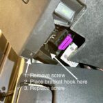
- Locate the Passenger Compartment Fuse Box: Refer to the description above to find its location under the right side of the instrument panel.
- Access the Fuse Panel: You may need a screwdriver or trim removal tool to open the fuse box cover.
- Identify Fuse #41: Use the diagram provided inside the fuse box cover or the fuse list above to locate fuse #41 (20A Mini).
- Inspect the Fuse: Visually check the fuse. A blown fuse will have a broken wire inside or blackened appearance. You can also use a fuse tester for a more definitive check.
- Replace the Fuse: If the fuse is blown, remove it and replace it with a new 20A Mini fuse. Ensure you use the correct amperage.
- Test the OBD2 Port: After replacing the fuse, try using your OBD2 scanner again to see if it’s now working.
Important Note: If the fuse blows again immediately after replacement, there is likely a more significant electrical issue, such as a short circuit. In such cases, it’s recommended to consult a qualified mechanic to diagnose and repair the underlying problem.
By following this guide, you should be able to quickly locate the OBD2 fuse in your 2007 Ford F-150 and take the first step in resolving any diagnostic port issues. Remember to always prioritize safety when working with your vehicle’s electrical system, and consult a professional if you are uncomfortable performing these checks yourself.