The 2008 Ford F-150, a popular and robust truck, relies on a complex electrical system to power its various components. Fuses play a crucial role in protecting this system from overloads, acting as safety valves that break circuits when excessive current flows through them. Understanding the fuse box locations and the function of each fuse is essential for troubleshooting electrical issues, including problems that might affect your On-Board Diagnostics II (OBD2) port.
This guide will provide you with a detailed overview of the fuse boxes in your 2008 Ford F-150, focusing on locations and diagrams to help you quickly identify fuses related to the OBD2 system and other vital vehicle functions. Knowing where these fuses are and what they control can save you time and money on repairs.
Understanding the Fuse Box Locations in Your 2008 Ford F-150
For the 2008 model year, the Ford F-150 is equipped with multiple fuse boxes strategically placed throughout the vehicle. This distribution helps to manage the electrical load and simplify circuit routing. Specifically, there are three main fuse box locations you should be aware of:
-
Passenger Compartment Fuse Panel: Located inside the cabin, this fuse box is typically found on the passenger side, often behind a panel in the dashboard or under the glove compartment. It houses fuses that protect circuits for interior components and some essential vehicle systems.
-
Auxiliary Relay Box (with DRL): This box is situated in the engine compartment. The “with DRL” designation indicates it is for models equipped with Daytime Running Lights (DRL).
-
Auxiliary Relay Box (without DRL): Also located in the engine compartment, this version is for 2008 Ford F-150 models that are not equipped with Daytime Running Lights.
It’s important to identify the correct fuse box diagram for your specific F-150 configuration, especially when dealing with the auxiliary relay boxes, as the presence or absence of DRLs affects the layout.
Passenger Compartment Fuse Panel Diagram
The passenger compartment fuse panel is a primary fuse distribution point. Here is a diagram and a detailed table outlining the fuses and relays within this panel. This is often the first place to check for issues related to interior electronics and some engine management systems.
This image shows the layout of the passenger compartment fuse panel in a 2008 Ford F-150.
| Type | No. | Description |
|---|---|---|
| Fuse MINI 10A | 1 | Run/Accessory – Wipers, Instrument cluster, Audio for XL/STX |
| Fuse MINI 20A | 2 | Stop/Turn lamps, ABS, T/T electric brake module, PCM (BOO signal), turn signal mirrors, CHMSL |
| Fuse MINI 5A | 3 | Power mirrors, Memory seats and pedals |
| Fuse MINI 10A | 4 | DVD battery power, Power fold mirror |
| Fuse MINI 5A | 5 | Keep alive memory for Powertrain Control Module (PCM) and Climate control module |
| Fuse MINI 15A | 6 | Parklamps, Body Security Module (BSM), Instrument panel illumination |
| Fuse MINI 5A | 7 | Radio (start signal) |
| Fuse MINI 10A | 8 | Heated mirrors, Switch indicator |
| Fuse MINI 20A | 9 | Fuel pump relay, Fuel injectors, Injector sense |
| Fuse MINI 20A | 10 | Trailer tow back-up lamps relay, Trailer tow parklamp relay |
| Fuse MINI 10A | 11 | A/C clutch, [4×4] solenoid |
| Fuse MINI 5A | 12 | PCM relay coil |
| Fuse MINI 10A | 13 | Climate control module power, Flasher relay |
| Fuse MINI 10A | 14 | Back-up lamp and Daytime Running Lamps (DRL) relay coil, A/C pressure switch, Redundant speed control switch, Heated PCV [5.4L], ABS |
| Fuse MINI 5A | 15 | Overdrive cancel, Cluster |
| Fuse MINI 10A | 16 | Brake-shift interlock solenoid |
| Fuse MINI 15A | 17 | Fog lamp relay |
| Fuse MINI 10A | 18 | Electrochromatic mirror, Heated seats, BSM, Compass, RSS (Reverse Sensing System), Power rail |
| Fuse MINI 10A | 19 | Restraints (Airbag module) |
| Fuse MINI 10A | 20 | Power rail |
| Fuse MINI 15A | 21 | Cluster keep alive power |
| Fuse MINI 10A | 22 | Delayed accessory power for audio, power door lock switch and moon roof switch illumination |
| Fuse MINI 10A | 23 | RH low beam headlamp |
| Fuse MINI 15A | 24 | Battery saver power for demand lamps, Flex fuel |
| Fuse MINI 10A | 25 | LH low beam headlamp |
| Fuse MINI 20A | 26 | Horn |
| Fuse MINI 5A | 27 | Passenger Airbag Deactivation (PAD) warning lamp, Cluster airbag warning lamp |
| Fuse MINI 5A | 28 | SecuriLock transceiver (PATS), PCM IGN monitor |
| Fuse MINI 15A | 29 | PCM [4×4] power |
| Fuse MINI 15A | 30 | PCM [4×4] power |
| Fuse MINI 20A | 31 | Radio power, Satellite radio module |
| Fuse MINI 15A | 32 | Vapor Management Valve (VMV), A/C clutch relay, Canister vent, Heated Exhaust Gas Oxygen (HEGO) sensors #11 and #21, CMCV, Mass Air Flow (MAF) sensor, Variable Cam Timing (VCT), Heated Positive Crankcase Ventilation (PCV) valve [4.2L engine], CID sensor [4.2L engine, 4.6L/4.2L EGR] |
| Fuse MINI 15A | 33 | Shift solenoid, CMS #12 and #22, Ignition coils |
| Fuse MINI 15A | 34 | PCM power, IMRC [4.2L] |
| Fuse MINI 20A | 35 | Instrument cluster high beam indicator, High beam headlamps, DRL disable relay |
| Fuse MINI 10A | 36 | Trailer tow right turn/stop lamps |
| Fuse MINI 20A | 37 | Rear power point |
| Fuse MINI 25A | 38 | Subwoofer power |
| Fuse MINI 20A | 40 | Low beam headlamps, DRL |
| Fuse MINI 10A | 42 | Trailer tow left turn/stop lamps |
| Fuse FMX/JCase 30A | 101 | Starter solenoid |
| Fuse FMX/JCase 20A | 102 | Ignition switch feed |
| Fuse FMX/JCase 20A | 103 | ABS valves |
| Fuse FMX/JCase 30A | 105 | Electric trailer brakes |
| Fuse FMX/JCase 30A | 106 | Trailer tow battery charge |
| Fuse FMX/JCase 30A | 107 | Power door locks (BSM) |
| Fuse FMX/JCase 30A | 108 | Passenger power seat |
| Fuse FMX/JCase 30A | 109 | Driver power seat, Adjustable pedals, Memory module (pedals, seats) |
| Fuse FMX/JCase 20A | 110 | Cigar lighter, Diagnostic connector power |
| Fuse FMX/JCase 30A | 111 | [4×4] motor relays |
| Fuse FMX/JCase 40A | 112 | ABS pump power |
| Fuse FMX/JCase 30A | 113 | Wipers and washer pump |
| Fuse FMX/JCase 40A | 114 | Heated backlite, Heated mirror power |
| Fuse FMX/JCase 20A | 115 | Moonroof |
| Fuse FMX/JCase 30A | 116 | Blower motor |
| Fuse FMX/JCase 20A | 117 | Instrument panel power point |
| Fuse FMX/JCase 30A | 118 | Heated seats |
| Circuit breaker MAXI | 401 | Delayed accessory power: Power windows, Power sliding backlite |
| Relay | R01 | Starter solenoid |
| Relay | R02 | Accessory delay |
| Relay | R03 | Hi-beam headlamps |
| Relay | R04 | Heated backlite |
| Relay | R05 | Trailer tow battery charge |
| Relay | R06 | Blower motor |
| Relay | R201 | Trailer tow park lamps |
| Relay | R202 | Fog lamps |
| Relay | R203 | PCM |
| Relay | R301 | Trailer tow backup lamps (Printed circuit board) |
| Relay | R303 | Fuel pump (Printed circuit board) |
| Relay | R304 | Battery saver (Printed circuit board) |
| Relay | R305 | Horn (Printed circuit board) |
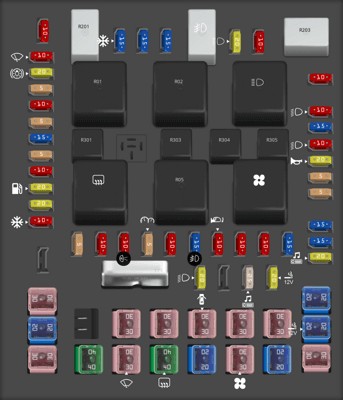

This table details each fuse and relay in the passenger compartment fuse panel of the 2008 Ford F-150, including their amperage and function.
Auxiliary Relay Box Diagram (with DRL)
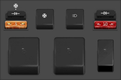
For 2008 Ford F-150 models equipped with Daytime Running Lights (DRL), the auxiliary relay box in the engine compartment has the following configuration. This box primarily manages relays and some fuses related to lighting and engine accessories.
This image illustrates the layout of the auxiliary relay box with Daytime Running Lights (DRL) for a 2008 Ford F-150.
| Type | No. | Description |
|---|---|---|
| Fuse ATO 5A | F03 | Clockspring illumination |
| Relay | R01 | [4×4] CCW |
| Relay | R02 | [4×4] CW |
| Relay | R03 | Daytime Running Lamps (DRL) High beam disable |
| Relay | R201 | DRL |
| Relay | R202 | A/C clutch |
| Diode ATO | D01 | A/C clutch |
| Diode ATO | D02 | One Touch Integrated Start (OTIS) |
This table lists the fuses, relays, and diodes found in the auxiliary relay box (with DRL) of a 2008 Ford F-150.
Auxiliary Relay Box Diagram (without DRL)
If your 2008 Ford F-150 does not have Daytime Running Lights, the auxiliary relay box in the engine compartment will have a slightly different configuration. Ensure you are using the correct diagram for accurate fuse and relay identification.
This image shows the configuration of the auxiliary relay box without Daytime Running Lights (DRL) in a 2008 Ford F-150.
| Type | No. | Description |
|---|---|---|
| Fuse ATO 5A | F03 | Clockspring illumination |
| Diode ATO | D01 | A/C clutch |
| Diode ATO | D02 | One Touch Integrated Start (OTIS) |
| Relay | R202 | A/C clutch |
This table details the components within the auxiliary relay box (without DRL) for a 2008 Ford F-150.
Locating the OBD2 Port and Identifying Related Fuses
The OBD2 port in a 2008 Ford F-150 is typically located beneath the dashboard on the driver’s side. It’s usually near the steering column or in the vicinity of the pedals. This port is crucial for diagnostics, allowing mechanics and vehicle owners to read trouble codes and access vehicle data using a scan tool.
While there isn’t a specific fuse labeled “OBD2 fuse,” several fuses are essential for the OBD2 port to function correctly. If you’re experiencing issues connecting your scan tool or suspect a problem with the OBD2 system, check the following fuses in the Passenger Compartment Fuse Panel:
- Fuse 110 (20A): Cigar lighter, Diagnostic connector power: This fuse directly powers the diagnostic connector, which is the OBD2 port. If this fuse is blown, the OBD2 port will likely not function.
- Fuse 5 (5A): Keep alive memory for Powertrain Control Module (PCM) and Climate control module: The PCM is the engine control computer, and it’s critical for OBD2 communication. While this fuse is for “keep alive memory,” issues here could indirectly affect OBD2 function.
- Fuse 28 (5A): SecuriLock transceiver (PATS), PCM IGN monitor: This fuse relates to the PCM ignition monitor, which is also important for overall PCM and potentially OBD2 operation.
- Fuses 29 & 30 (15A): PCM [4×4] power & Fuse 34 (15A): PCM power, IMRC [4.2L]: These fuses provide power to the Powertrain Control Module (PCM). Without proper PCM power, the OBD2 system will not operate.
By checking these fuses, you can often resolve issues related to a non-functioning OBD2 port. Always replace a blown fuse with one of the same amperage rating to avoid further electrical problems.
Conclusion
Understanding the fuse box locations and fuse functions in your 2008 Ford F-150 is a valuable skill for any owner. By using these diagrams and fuse descriptions, you can effectively troubleshoot electrical problems and maintain your vehicle. Remember to always consult your owner’s manual for the most accurate information and consider seeking professional help from a certified mechanic if you are uncomfortable working with automotive electrical systems. Regular fuse checks can prevent minor issues from becoming major repairs, keeping your Ford F-150 running reliably for years to come.