Are you struggling to get your CAN bus shield to communicate with your car’s OBD2 port using a DB9 connector? Many DIY enthusiasts and car hackers encounter challenges when trying to bridge the gap between older DB9 interfaces and the modern OBD2 standard. If you’re pulling your hair out trying to read engine RPM, speed, or other vital data for your custom car projects, you’re not alone. This guide will walk you through common pitfalls and troubleshooting steps to get your Db9 To Obd2 connection working smoothly.
Connecting to your car’s On-Board Diagnostics II (OBD2) system opens up a world of data for custom instrument clusters, performance monitoring, and deeper automotive insights. However, if you’re using a CAN bus shield that relies on a DB9 connector, interfacing with the OBD2 port requires a proper DB9 to OBD2 cable. Let’s dive into the potential roadblocks and how to overcome them.
Understanding the DB9 to OBD2 Challenge
The original poster in our forum is facing a common issue: a seemingly correct setup that just won’t transmit or receive data from the OBD2 port. They’re using a Seeed CAN shield V2.0 and a DIY DB9 to OBD2 cable, aiming to read standard OBD2 PIDs (Parameter IDs) like engine RPM and vehicle speed. Despite trying example code and verifying their cable wiring, they’re hitting a wall.
Here are the core issues we’ll address, mirroring the original poster’s experience:
- No data reception: The CAN shield sends requests, but no response is received from the car’s OBD2 system.
- Unusual “spamming” behavior: The CAN shield appears to continuously transmit even after sending a single command.
- Uncertainty about cable wiring: DIY DB9 to OBD2 cables can be tricky to wire correctly, and incorrect wiring is a primary suspect.
- Shield functionality doubts: Without another shield for testing, it’s hard to confirm if the shield itself is working correctly.
Diagnosing Your DB9 to OBD2 Setup
Let’s break down the troubleshooting process step-by-step, focusing on the “db9 to obd2” connection point and related components.
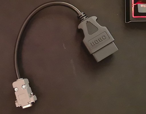
1. Verifying Your DB9 to OBD2 Cable: The Prime Suspect
A DIY DB9 to OBD2 cable is often the most likely source of connection problems. OBD2 ports have a standardized pinout, and CAN bus communication uses specific pins. Similarly, DB9 connectors have their own pin assignments, which need to be correctly mapped to the OBD2 side.
Key things to check:
- Wiring Diagram Accuracy: Double and triple-check your wiring diagram against reliable sources. Different sources online can sometimes have errors. Ensure you’re using a diagram specifically for CAN bus over OBD2 and DB9. For OBD2 CAN, you’re typically interested in pins 6 (CAN High) and 14 (CAN Low). On the DB9 side, CAN High and CAN Low pin assignments can vary depending on the specific CAN shield or device you’re using. Refer to your CAN shield’s documentation for the correct DB9 pinout for CAN.
- Continuity Testing: Use a multimeter to perform continuity tests on your DIY cable. Verify that each pin on the DB9 connector is correctly connected to the corresponding pin on the OBD2 connector according to your chosen wiring diagram. This step is crucial to eliminate wiring errors.
- Ground and Power: While CAN communication primarily relies on CAN High and CAN Low, ensure you have proper ground connections in your DB9 to OBD2 cable if required by your CAN shield or setup. Some setups might also utilize power from the OBD2 port, so verify if your shield needs it and if your cable provides it correctly.
If you’re unsure about your DIY cable, consider these options:
- Pre-made DB9 to OBD2 Cable: Purchase a commercially available, pre-made DB9 to OBD2 cable specifically designed for CAN bus applications. This eliminates the DIY wiring variable and ensures a known good cable.
- OBD2 Breakout Box: Use an OBD2 breakout box. This device plugs into your car’s OBD2 port and provides labeled screw terminals or pin headers for each OBD2 pin. This makes it easier to connect jumper wires to your CAN shield and test connections without a potentially faulty DIY cable.
2. Investigating the CAN Shield and “Spamming” Behavior
The original poster observed that their Seeed CAN shield seemed to “spam” messages continuously. Let’s analyze this:
- Normal Behavior?: It’s not necessarily abnormal for a CAN device to transmit repeatedly, especially if it’s sending requests and not receiving expected responses. The shield might be configured to retry sending a request until it gets an acknowledgment or data back.
- Code Configuration: Review your code. Is there any loop or setting that might be causing continuous transmission? However, based on the description, the “spamming” persists even after uploading different code, suggesting it might be a lower-level behavior of the shield itself when it doesn’t establish proper communication.
- Shield Functionality Test: If possible, try testing your CAN shield in a different setup. Do you have another CAN device you can communicate with to verify the shield is sending and receiving CAN messages correctly in isolation, without the OBD2 connection? This can help isolate whether the issue lies with the shield itself or the DB9 to OBD2 interface.
- Termination Resistor: CAN bus networks often require a 120-ohm termination resistor at each end of the bus to prevent signal reflections. Some CAN shields have a built-in termination resistor that can be enabled/disabled via a jumper or switch. Check your shield’s documentation and ensure the termination resistor is configured appropriately for your setup (typically, you need one termination resistor in a simple point-to-point connection like OBD2 to shield).
The oscilloscope image from the original post does show CAN bus activity. This suggests the shield is transmitting, but the problem is likely with receiving data back from the OBD2 port, or the data being transmitted is not correctly formed or understood by the car’s ECU.
3. OBD2 Port and Car Compatibility
While OBD2 is a standard, some vehicles might have variations or specific implementation quirks.
- OBD2 Scanner Verification: The original poster confirmed their OBD2 port works with a standard OBD2 scanner. This is a good baseline check. If your OBD2 port didn’t work with a regular scanner, that would indicate a problem with the car’s OBD2 system itself.
- Protocol Compatibility: OBD2 uses various communication protocols (CAN, ISO 9141-2, etc.). Modern vehicles heavily rely on CAN bus (ISO 15765-4). Your CAN shield and code should be configured to use the correct CAN protocol and baud rate (typically 500kbps or 250kbps for automotive CAN). The provided code examples seem to be configured for 500kbps, which is common for OBD2 CAN.
- ECU Response and PIDs: Even with a correct connection, the car’s Engine Control Unit (ECU) needs to respond to your requests for specific PIDs. Not all vehicles support all OBD2 PIDs. Start with very basic, commonly supported PIDs like
0x0C(Engine RPM) and0x0D(Vehicle Speed), as used in the example code. If those don’t work, it’s less likely to be a PID-specific issue and more likely a connection or basic communication problem.
4. Code Review: Basic OBD2 Request Structure
Let’s briefly look at the provided code snippets. The code examples seem to follow a standard OBD2 request structure:
- Request ID (Arbitration ID):
0x7DFis the standard functional request ID for OBD2. - Data Bytes:
0x02: Service 01 (Show current data) and number of data bytes following.0x01: Service 01 code.0x0C(or0x0D,0x05): PID (Parameter ID) you’re requesting (Engine RPM, Vehicle Speed, Coolant Temp).0x55(or0x00): Padding bytes (often unused and filled with0x55or0x00).
The code structure appears generally correct for sending a basic OBD2 Mode 01 request. However, code issues are less likely to be the primary problem if the basic connection and wiring are not properly established.
Systematic Troubleshooting Steps:
- Prioritize Cable Verification: Start by meticulously verifying your DB9 to OBD2 cable wiring. Continuity testing is essential. Consider using a pre-made cable or OBD2 breakout box to eliminate cable issues.
- Isolate Shield Functionality: Test your CAN shield in a simpler CAN bus setup without the OBD2 connection if possible.
- Double-Check Code Configuration: Ensure your code is configured for the correct CAN baud rate (500kbps or 250kbps), and you’re using basic OBD2 request structures.
- Start with Basic PIDs: Request commonly supported PIDs like Engine RPM and Vehicle Speed.
- Monitor CAN Bus Traffic (Optional but helpful): If you have a CAN bus analyzer or a more advanced oscilloscope, monitor the CAN bus traffic to see exactly what’s being transmitted and if there are any responses from the car.
- Review Shield and Vehicle Documentation: Refer to the documentation for your specific CAN shield and, if possible, your vehicle’s service information regarding OBD2 and CAN bus implementation.
Conclusion: Persistence and Precision
Troubleshooting DB9 to OBD2 connections for CAN bus can be frustrating, but by systematically checking each component – especially the cable wiring – and understanding the basics of OBD2 communication, you can pinpoint the problem. Focus on eliminating potential points of failure one by one. Accurate wiring, correct code configuration, and understanding the expected behavior of your CAN shield are key to successfully reading data from your car’s OBD2 port and bringing your automotive projects to life.