Want to delve into the world of car diagnostics without breaking the bank? Building your own Diy Obd2 Usb Cable is a fantastic project for any car enthusiast or DIYer. This guide will walk you through the process of creating a simple yet effective OBD2 to USB cable, allowing you to connect your car to a computer for reading diagnostic data. Please remember, this is a DIY project and should be undertaken at your own risk. We are not responsible for any issues arising from following this guide, including damage to your vehicle’s ECU or any unforeseen interdimensional consequences.
Tools and Parts You’ll Need
Before you get started, gather these essential tools and parts. Having everything prepared will make the process smoother and more efficient.
- Wire strippers/cutters
- Needle-nose pliers
- Molex crimping tool (optional, but recommended for a professional crimp)
- Soldering iron and solder (recommended for a robust connection)
- 4-pin connector (Link to part – suitable for 22-16AWG wire, 1.3-1.7mm insulation)
- OBD-II Cable (Link to part)
If you happen to have spare wires lying around, you can save a bit by purchasing just the female OBD-II connector and wiring the necessary 4 wires directly between it and the 4-pin connector. Just ensure you know the wire gauge you have to select the correct 4-pin connector.
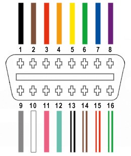
For this diy obd2 usb cable, we will only be utilizing 4 out of the 16 wires on the OBD-II connector (referred to as OBD2C). These are crucial for basic OBD2 communication:
- Pin 4 (Chassis ground; orange wire on OBD2C)
- Pin 6 (CAN [J-2234] High; green wire on OBD2C)
- Pin 14 (CAN [J-2234] Low; brown w/white stripe wire on OBD2C)
- Pin 16 (Battery power; green w/white stripe wire on OBD2C)
Step-by-Step Guide to Building Your DIY OBD2 USB Cable
Let’s get into the actual construction of your diy obd2 usb cable. Follow these steps carefully to ensure a successful build.
Step 1: Preparing the OBD-II Cable Wires
Based on common practices for CAN bus wiring, it’s advisable to twist wire pairs to minimize interference. Begin by carefully removing the outer sheath and shielding from the OBD2C cable. Isolate the four wires you’ll be using (pins 4, 6, 14, and 16) and set aside the remaining 12 wires, securing them with a zip-tie to keep them out of your workspace.
Step 2: Preparing the 4-Pin Connector Pins
A slight challenge with the chosen parts is the wire gauge of the OBD2C (26AWG) being smaller than ideal for the 4-pin connector pins (designed for 22AWG). To compensate for this, carefully strip approximately 3/8″ of insulation from the ends of the four wires. Fold the exposed wire strands back onto themselves and twist them to effectively thicken the wire, ensuring a better fit within the pin connector. Before proceeding, slide a rubber seal (included with the 4-pin connector kit) onto each of the four wires.
Step 3: Connecting Wires to Pins – Soldering or Crimping
The pins for the 4-pin connector feature two sets of prongs. The front prongs are designed to clamp onto the exposed wire, while the rear prongs secure the rubber seal. Insert the prepared wire into the pin, ensuring it aligns with the front prongs. Due to the thin gauge of the wire, using needle-nose pliers to hold the wire in place during the next step is highly recommended.
For a reliable connection, soldering the wire to the pin connector is highly recommended. Soldering provides a solid mechanical and electrical bond, which is particularly beneficial given the small wire size. If you’re new to soldering, numerous online resources, such as this helpful YouTube video, can provide valuable tips and techniques.
Alternatively, if you possess a Molex crimping tool, you can crimp the connector prongs onto the wire.
If you opt for crimping without a specialized tool, needle-nose pliers can be used. Carefully fold one prong at a time over the wire, using the pliers at an angle to gradually crimp the metal. This YouTube video offers guidance on crimping techniques using pliers. For added security, you can gently squeeze the crimped prongs further with the pliers, though this might be considered overkill.
Step 4: Assembling the 4-Pin Connector
Slide the rubber seal up the wire until it sits between the rear set of prongs on the connector pin. Employ the same crimping technique used for the wire prongs to fold these rear prongs over the rubber seal, securing it in place. Repeat steps 3 and 4 for all four wires and connector pins.
Step 5: Inserting Pins into the 4-Pin Connector Housing
While the reason isn’t explicitly stated in all guides, it’s often recommended to twist specific wire pairs together. Pair and twist the wires as follows:
- Pin 4 (orange) with Pin 16 (green w/white stripe)
- Pin 6 (green) with Pin 14 (brown w/white stripe)
Insert the prepared pins into the 4-pin connector housing in the following orientation:
- Pin 14 (brown w/white stripe) > Connector slot A
- Pin 6 (green) > Connector slot B
- Pin 16 (green w/white stripe) > Connector slot C
- Pin 4 (orange) > Connector slot D
Push each pin into the rear of the connector housing until you hear a distinct click, indicating it is securely locked in place. Needle-nose pliers can be helpful to gently pull the wire from the front to ensure the pin is fully seated and locked.
Testing Your DIY OBD2 USB Cable
Congratulations! You’ve built your diy obd2 usb cable.
Now it’s time to test your creation. Connect your DIY cable to your vehicle’s OBD2 port and to your computer. Use compatible OBD2 diagnostic software to check for connectivity and attempt to read vehicle data. The cable has been successfully tested for reading and clearing error codes (including self-induced ones! :D).
If any step in this guide is unclear, please ask for clarification! We can provide additional photos or explanations to help you successfully build your own diy obd2 usb cable.