Are you looking to connect your OBD2 diagnostic scanner to a vehicle with a non-standard OBD2 port, or perhaps need a custom OBD2 adapter for a specific project? Building your own OBD2 adapter harness is a straightforward task that can save you money and provide a tailored solution. This guide will walk you through the process of creating a simple yet effective OBD2 adapter using readily available components.
This DIY project is designed for individuals with basic automotive knowledge and some comfort with simple wiring tasks. While we aim to provide clear and accurate instructions, please remember that working with automotive electrical systems carries inherent risks. Proceed at your own risk, and always prioritize safety. We are not responsible for any damage or issues that may arise from following this guide.
Tools and Parts You’ll Need
Before you begin, gather the necessary tools and parts. Having everything prepared beforehand will make the process smoother and more efficient.
Tools:
- Wire strippers/cutters
- Needle-nose pliers
- Molex crimping tool (optional, but recommended for professional crimps)
- Soldering iron and solder (recommended for enhanced connection reliability)
Parts:
- 4-Pin Connector Kit (Corsa Technic – 4-Pin Connector) – Ensure it’s suitable for 22-16AWG wire and 1.3-1.7mm insulation.
- OBD-II Cable (Corsa Technic – OBD-II Cable) – This cable comes with a female OBD-II connector and wires.
Alternative Parts (Saving Costs):
If you have spare automotive wire, you can reduce costs by purchasing only the female OBD-II connector and using your own wire to connect it to the 4-pin connector. Ensure your wire gauge is compatible with the 4-pin connector pins (22-16AWG).
Understanding the OBD2 Connector Wiring
The OBD-II connector, or OBD2 connector, has 16 pins, but for many basic diagnostic purposes, we only need to focus on four key pins. These pins are crucial for CAN bus communication, which is the standard protocol for vehicle diagnostics in most modern cars.
The OBD-II cable (OBD2C) we’re using provides color-coded wires connected to these essential pins:
- Pin 4: Chassis Ground (Orange wire on OBD2C) – Provides the ground reference for the electrical circuit.
- Pin 6: CAN High (CAN [J-2234] High; Green wire on OBD2C) – Carries the CAN bus high signal for communication.
- Pin 14: CAN Low (CAN [J-2234] Low; Brown w/white stripe wire on OBD2C) – Carries the CAN bus low signal for communication.
- Pin 16: Battery Power (Green w/white stripe wire on OBD2C) – Provides 12V power to the OBD2 device.
These four pins are sufficient for connecting many OBD2 scanners and devices that utilize the CAN protocol.
Step-by-Step Guide to Building Your OBD2 Adapter Harness
Now, let’s proceed with the step-by-step instructions to assemble your custom OBD2 adapter.
Step 1: Prepare the OBD-II Cable Wires
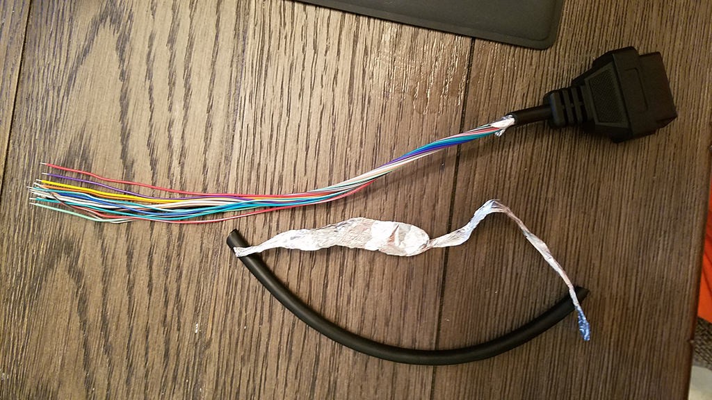
The OBD-II cable comes with a protective sheath and shielding around the wires. We need to access the four essential wires and prepare them for connection.
- Carefully remove the outer sheath and shielding from the end of the OBD-II cable to expose the wires.
- Identify the four wires we need: orange (Pin 4), green (Pin 6), brown w/white stripe (Pin 14), and green w/white stripe (Pin 16).
- Separate these four wires from the rest. Bundle the remaining 12 wires together and secure them with a zip tie to keep them out of the way during the adapter assembly.
Step 2: Prepare the Wire Ends for the 4-Pin Connector
The wires in the OBD-II cable are 26AWG, which is slightly smaller than the 22AWG size that the pins of the 4-pin connector (4PC) are ideally designed for. To ensure a secure connection, we’ll thicken the wire ends.
- The wires come pre-stripped with a small amount of exposed wire. Strip off an additional amount of insulation from the end of each of the four wires, exposing about 3/8 inch of bare wire.
- Fold the exposed wire over on itself to double its thickness.
- Twist the folded wire to create a thicker strand that will fit more snugly into the 4-pin connector pins.
- Take one of the rubber seals from the 4-pin connector kit and slide it onto each of the prepared wires. These seals will provide environmental protection to the connection.
Step 3: Position the Wire in the 4-Pin Connector Pin
The pins for the 4-pin connector have two sets of prongs. The front prongs are designed to crimp onto the bare wire, and the rear prongs crimp onto the wire insulation (over the rubber seal).
- Insert the prepared wire into a 4-pin connector pin, ensuring the exposed wire is positioned between the front set of prongs.
- Use needle-nose pliers to hold the wire in place. This is particularly helpful because the 26AWG wire is quite thin compared to the pin connector.
Step 4: Solder the Wire to the Pin (Recommended)
Soldering provides a robust and electrically sound connection, especially when dealing with smaller gauge wires.
- Carefully solder the wire to the 4-pin connector pin. Ensure the solder flows and creates a solid connection between the wire and the pin.
- If you are new to soldering, there are many helpful resources available online. This YouTube video offers useful soldering tips and techniques.
Step 5: Crimp the Front Prongs of the Connector Pin
If you have a Molex crimping tool, this is the ideal tool for crimping the connector prongs. If not, needle-nose pliers can be used with care.
- Using a Crimping Tool (Recommended): Position the pin in the Molex crimping tool according to the tool’s instructions and crimp the front prongs down onto the wire.
- Using Needle-Nose Pliers: If you don’t have a crimping tool, use needle-nose pliers to carefully fold one of the front prongs over the wire. Then, fold the other prong over, ensuring a secure grip on the wire. This YouTube video demonstrates crimping techniques with pliers.
- For added security, you can use the pliers to gently crush the prongs further down, ensuring a tight mechanical connection.
Step 6: Crimp the Rear Prongs Over the Rubber Seal
Now, we need to crimp the rear set of prongs on the connector pin over the rubber seal to provide strain relief and environmental protection.
- Slide the rubber seal up the wire until it is positioned between the rear set of prongs on the connector pin.
- Use the same crimping technique as in Step 5 (either with a crimping tool or needle-nose pliers) to fold the rear prongs over the rubber seal.
Step 7: Twist Wire Pairs (Recommended)
While not strictly mandatory, twisting wire pairs is a good practice to reduce electromagnetic interference (EMI).
- Pair the wires as follows:
- Pin 4 (orange) with Pin 16 (green w/white stripe)
- Pin 6 (green) with Pin 14 (brown w/white stripe)
- Twist each pair of wires together. This helps in noise cancellation and ensures signal integrity, especially for CAN bus communication.
Step 8: Insert Pins into the 4-Pin Connector Housing
Finally, insert the completed pins into the 4-pin connector housing in the correct orientation.
-
Refer to the pinout diagram for the 4-pin connector:
- Connector slot A: Pin 14 (brown w/white stripe) – CAN Low
- Connector slot B: Pin 6 (green) – CAN High
- Connector slot C: Pin 16 (green w/white stripe) – Battery Power
- Connector slot D: Pin 4 (orange) – Chassis Ground
-
Insert each pin into the rear of the 4-pin connector housing, matching the wire to the correct slot as per the diagram above.
-
Push the pin in until you hear an audible “click,” indicating that it is locked securely in place. You can use needle-nose pliers to gently pull the wire from the front to ensure it is locked in.
Testing Your OBD2 Adapter
Congratulations! You have built your custom OBD2 adapter. Before using it extensively, it’s crucial to test it to ensure it functions correctly.
- Connect your newly built OBD2 adapter to your vehicle’s OBD2 port and your OBD2 diagnostic scanner.
- Turn on your vehicle’s ignition.
- Use your OBD2 scanner to attempt to connect to the vehicle’s ECU (Engine Control Unit).
- Check if you can read diagnostic trouble codes (DTCs) or access live data.
- If possible, perform a simple function like clearing a non-critical diagnostic code to verify bidirectional communication.
Safety Precautions
- Disconnect the vehicle battery: While this is a low-power circuit, it’s always a good safety practice to disconnect the negative terminal of your vehicle’s battery before working on any electrical components.
- Double-check wiring: Before connecting your adapter, meticulously double-check your wiring against the pinout diagrams to prevent short circuits or damage to your vehicle’s ECU or your OBD2 scanner.
- Use proper tools: Employ the correct tools for stripping, crimping, and soldering wires to ensure secure and reliable connections.
- Work in a well-lit area: Ensure you have adequate lighting to clearly see the small components and wiring.
- If unsure, seek professional help: If you are uncomfortable with any step or unsure about your wiring, consult a qualified automotive technician.
Conclusion
Building your own OBD2 adapter is a rewarding DIY project that provides a practical solution for custom diagnostic needs. By following this guide, you can create a functional OBD2 adapter harness using basic tools and readily available parts. This custom adapter can be invaluable for working with various vehicles or specific automotive projects. Remember to always prioritize safety and double-check your work to ensure proper and reliable operation of your OBD2 adapter.