Are you looking to connect your standard OBD2 diagnostic scanner to a vehicle or system that utilizes a 4-pin connector? Many older vehicles or specialized equipment don’t feature the universally adopted OBD2 port. In these scenarios, creating a custom Obd2 4 Pin Adapter becomes essential. This guide provides a step-by-step walkthrough on how to build your own adapter, allowing you to bridge the gap and access diagnostic information.
Disclaimer: While this guide aims to provide clear instructions, always exercise caution when working with vehicle electronics. Incorrect wiring can potentially damage your vehicle’s systems or diagnostic tools. Proceed at your own risk. The author and website are not responsible for any damage resulting from following these instructions.
Tools and Parts You’ll Need
To embark on this DIY project, gather the following tools and parts:
- Wire strippers/cutters: For preparing the wires.
- Needle-nose pliers: Helpful for handling small components and crimping.
- Molex crimping tool (Recommended): Ensures a professional and secure crimp (though alternatives are discussed).
- Soldering iron (Optional but Recommended): For a robust and reliable electrical connection.
- 4-pin connector: This is the heart of your adapter, designed to mate with the 4-pin port on your vehicle or system. Ensure it’s compatible with your application. (Example Part: 4-Pin Connector; pin/wire size = 22-16AWG; insulation/seal size = 1.3-1.7mm)
- OBD-II Cable: Provides the standard OBD2 connector to interface with your scanner. (Example Part: OBD-II Cable)
If you have spare automotive wire, you can opt to purchase just the female OBD-II connector and wire the necessary connections directly to the 4-pin connector, potentially saving on costs. However, ensure your wire gauge is compatible with the selected 4-pin connector pins.
Understanding the Wiring: OBD2 to 4-Pin
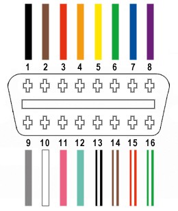
The standard OBD2 connector (OBD2C) features 16 pins, but for our OBD2 4 pin adapter, we will only utilize four crucial wires. These wires carry the essential signals for basic diagnostic communication:
- Pin 4 (Chassis Ground): Provides the ground reference for the electrical circuit (Orange wire in the example OBD2C).
- Pin 6 (CAN [J-2284] High): Carries the CAN bus high signal, part of the Controller Area Network communication protocol used in many vehicles (Green wire in the example OBD2C).
- Pin 14 (CAN [J-2284] Low): Carries the CAN bus low signal, the counterpart to CAN High (Brown with white stripe wire in the example OBD2C).
- Pin 16 (Battery Power): Supplies power to the OBD2 scanner (Green with white stripe wire in the example OBD2C).
Step-by-Step Guide: Building Your OBD2 4-Pin Adapter
Let’s proceed with the construction of your OBD2 4 pin adapter. Follow these steps carefully:
Step 1: Preparing the OBD-II Cable Wires
- Expose the Wires: Begin by carefully removing the outer sheath and shielding from the OBD-II cable to access the individual wires.
- Isolate the Four Essential Wires: Identify and separate the four wires corresponding to pins 4, 6, 14, and 16 as listed above (Ground, CAN High, CAN Low, and Power).
- Organize Remaining Wires: Bundle the remaining 12 wires from the OBD-II cable and secure them with a zip tie to keep them out of the way and prevent accidental shorts.
Step 2: Preparing the 4-Pin Connector Pins
- Address Wire Gauge Mismatch: The wires in the example OBD-II cable are 26AWG, slightly smaller than the 22AWG-sized pins of the 4-pin connector kit. To compensate for this:
- Strip approximately 3/8″ of insulation from the end of each of the four wires.
- Fold the exposed wire strands over onto themselves and twist them tightly. This “thickens” the wire to ensure a better fit within the connector pins.
- Slide on Rubber Seals: The 4-pin connector kit should include rubber seals. Slide one seal onto each of the prepared wires. These seals provide environmental protection at the connector.
Step 3: Soldering or Crimping the Wires to the Pins
- Pin Structure: Observe the pins of the 4-pin connector. They have two sets of prongs. The front prongs are designed to clamp onto the wire strands, and the rear prongs secure the rubber seal.
- Wire Insertion: Insert the prepared wire into the front of a pin, ensuring the exposed wire is positioned to be clamped by the front prongs.
- Soldering (Recommended): For a highly reliable connection, soldering is recommended, especially given the wire size discrepancy.
- Apply solder to the wire where it meets the pin. Ensure the solder flows smoothly, creating a solid mechanical and electrical bond.
- For soldering tips, refer to online resources like this helpful YouTube video.
- Crimping (Alternative): If you have a Molex crimping tool, use it for a professional crimp.
- Position the pin and wire in the crimping tool.
- Apply firm, even pressure to crimp the front prongs securely around the wire.
- If a crimping tool isn’t available, needle-nose pliers can be used carefully. Gently fold one prong at a time over the wire, ensuring a tight grip.
- This YouTube video demonstrates crimping techniques with pliers.
Step 4: Securing the Rubber Seal and Assembling the Connector
- Slide Seal into Position: Slide the rubber seal up the wire until it sits between the rear prongs of the connector pin.
- Crimp Rear Prongs: Using your crimping tool or needle-nose pliers, fold the rear prongs over the rubber seal. This secures the seal and provides strain relief and environmental protection.
Step 5: Assembling the 4-Pin Connector Housing
-
Wire Pairing (Recommended): While not definitively proven to be essential, many guides recommend twisting pairs of wires. Pair and twist the wires as follows:
- Pin 4 (Orange – Ground) / Pin 16 (Green w/white stripe – Power)
- Pin 6 (Green – CAN High) / Pin 14 (Brown w/white stripe – CAN Low)
-
Insert Pins into Connector Housing: Refer to the diagram below for the correct pin insertion orientation into the 4-pin connector housing. Insert each pin into its designated slot from the rear of the connector until you hear an audible “click,” indicating it is locked in place. You may find needle-nose pliers helpful to gently pull the wire from the front to ensure the pin is fully seated and locked.
- Slot A: Pin 14 (Brown w/white stripe – CAN Low)
- Slot B: Pin 6 (Green – CAN High)
- Slot C: Pin 16 (Green w/white stripe – Power)
- Slot D: Pin 4 (Orange – Ground)
Completion and Testing
Congratulations! Your OBD2 4 pin adapter is now complete.
Before using it for critical diagnostics, it’s advisable to test the adapter. In the original guide, the creator successfully used the adapter to check and clear a self-induced error code.
This DIY OBD2 4 pin adapter project empowers you to connect standard OBD2 diagnostic tools to systems utilizing a 4-pin interface. By carefully following these steps and exercising due diligence, you can create a valuable tool for vehicle diagnostics and troubleshooting.