In today’s technologically advanced automotive landscape, understanding your vehicle’s health is more accessible than ever, thanks to On-Board Diagnostics II (OBD2). At the heart of this system lies a crucial component: the Obd2 Data Link Connector. This unassuming port is your gateway to a wealth of information about your car’s performance and potential issues.
Think of the OBD2 data link connector as your car’s diagnostic front door. It’s a standardized interface that allows mechanics and car owners alike to tap into the intricate network of sensors and computers within a vehicle. By connecting a compatible scan tool or diagnostic device to this connector, you can retrieve real-time data, diagnose problems, and ensure your vehicle is running optimally. This article will delve deep into the world of the OBD2 data link connector, exploring its function, standards, and why it’s an indispensable part of modern vehicle maintenance and diagnostics. Whether you’re a seasoned mechanic or a curious car owner, understanding the OBD2 data link connector is key to unlocking your vehicle’s diagnostic potential.
Decoding the OBD2 Data Link Connector
The OBD2 Data Link Connector (DLC), often simply referred to as the OBD2 connector or port, is a standardized 16-pin interface found in virtually all cars and light trucks manufactured since the mid-1990s. Its primary purpose is to provide access to the vehicle’s diagnostic system, enabling the retrieval of diagnostic trouble codes (DTCs), live sensor data, and other valuable information. This standardization is a cornerstone of OBD2, ensuring that regardless of the vehicle manufacturer, a compatible diagnostic tool can be used to communicate with the car’s computer systems.
Location of the OBD2 Connector
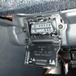
Finding the OBD2 data link connector in your vehicle is usually straightforward. The Society of Automotive Engineers (SAE) standard J1962 mandates that the connector be located within the passenger compartment, easily accessible to the driver. Typically, you’ll find it under the dashboard on the driver’s side. Common locations include:
- Below the steering column: This is perhaps the most frequent location, often directly beneath the dashboard and above the pedals.
- To the left or right of the steering column: Sometimes, the connector might be slightly offset to either side of the steering column, still within easy reach.
- Near the center console: In some vehicles, particularly larger ones, the OBD2 port could be located closer to the center console area, still within the front passenger compartment.
- Behind an access panel: Less commonly, the connector might be hidden behind a small access panel, which can usually be easily opened without tools.
While the location is generally standardized for ease of access, it’s always a good idea to consult your vehicle’s owner’s manual if you’re having trouble locating the OBD2 data link connector. Online resources and vehicle-specific forums can also provide helpful guidance.
Unpacking the OBD2 DLC Pinout: SAE J1962 Standard
The SAE J1962 standard meticulously defines the pinout of the OBD2 data link connector, ensuring interoperability across different vehicle makes and models. This 16-pin connector is not just a random arrangement; each pin is assigned a specific function, facilitating various communication protocols and power delivery. Let’s break down the function of each pin in a typical Type A OBD2 connector:
- Pin 1: Manufacturer Discretionary (MD) / Optional: This pin is often manufacturer-specific and may be used for various purposes, or may be left unconnected. Its function varies widely between vehicle brands.
- Pin 2: SAE J1850 Bus Positive (VPW/PWM): Used for SAE J1850 VPW (Variable Pulse Width Modulation) and PWM (Pulse Width Modulation) communication protocols, primarily found in older Ford and GM vehicles.
- Pin 3: Manufacturer Discretionary (MD) / Optional: Similar to Pin 1, this is another pin designated for manufacturer-specific use and can have diverse functions or be unused.
- Pin 4: Chassis Ground: Provides a ground connection to the vehicle’s chassis, essential for electrical grounding of diagnostic tools.
- Pin 5: Signal Ground: Another ground pin, providing a signal ground reference for communication circuits, ensuring signal integrity.
- Pin 6: CAN High (ISO 15765-4 & SAE J2284): This is a critical pin for modern vehicles, carrying the CAN High signal for the CAN (Controller Area Network) bus communication protocol, as defined by ISO 15765-4 and SAE J2284 standards. CAN bus is the backbone of OBD2 communication in most vehicles manufactured post-2008.
- Pin 7: ISO 9141-2 K-line & ISO 14230-4 K-line: Used for ISO 9141-2 and ISO 14230-4 (Keyword Protocol 2000 or KWP2000) communication protocols, found in some older European and Asian vehicles.
- Pin 8: Manufacturer Discretionary (MD) / Optional: Yet another pin reserved for manufacturer-defined purposes, offering flexibility for specific vehicle systems or features.
- Pin 9: Manufacturer Discretionary (MD) / Optional: Like Pins 1, 3, and 8, this pin’s function is at the discretion of the vehicle manufacturer.
- Pin 10: SAE J1850 Bus Negative (PWM only): Used for the SAE J1850 PWM communication protocol, carrying the negative signal for this system.
- Pin 11: Manufacturer Discretionary (MD) / Optional: Continuing the trend, this pin is also for manufacturer-specific applications.
- Pin 12: Manufacturer Discretionary (MD) / Optional: Another manufacturer discretionary pin, highlighting the flexibility built into the OBD2 standard.
- Pin 13: Manufacturer Discretionary (MD) / Optional: One more pin that can be customized by vehicle manufacturers for their own systems.
- Pin 14: CAN Low (ISO 15765-4 & SAE J2284): The counterpart to Pin 6, this pin carries the CAN Low signal for CAN bus communication. Together, Pins 6 and 14 form the CAN bus interface within the OBD2 connector.
- Pin 15: ISO 9141-2 L-line & ISO 14230-4 L-line: Used for the L-line in ISO 9141-2 and ISO 14230-4 communication, though the K-line (Pin 7) is more commonly used in these protocols.
- Pin 16: Battery Voltage (12V or 24V): Provides battery power to the diagnostic tool connected to the OBD2 port. Type A connectors typically supply 12V, common in cars, while Type B connectors, used in medium and heavy-duty vehicles, supply 24V.
Understanding this pinout is crucial for anyone developing OBD2 diagnostic tools or attempting to interface directly with a vehicle’s diagnostic system. It ensures correct connections and proper communication, preventing potential damage to the vehicle’s electronic systems or the diagnostic equipment.
OBD2 Connector Types: Type A vs. Type B (SAE J1962)
While the 16-pin structure is consistent, the SAE J1962 standard defines two primary connector types: Type A and Type B. The key difference lies in their voltage supply and physical keying, primarily designed to differentiate between passenger vehicles (cars and light trucks) and heavier vehicles.
-
Type A OBD2 Connector: This is the most common type, found in passenger cars and light-duty vehicles. It provides a 12V power supply on Pin 16 and features a single, unbroken groove in the connector housing.
-
Type B OBD2 Connector: Predominantly used in medium and heavy-duty vehicles (trucks, buses), the Type B connector provides a 24V power supply on Pin 16. Visually, it’s distinguished by an interrupted groove in the center of the connector housing. This interrupted groove is a keying feature, preventing a Type A connector (designed for 12V systems) from being accidentally plugged into a 24V Type B socket, which could damage 12V-based diagnostic equipment.
It’s worth noting that while a Type B OBD2 adapter cable is designed to be compatible with both Type A and Type B sockets due to the interrupted groove, a Type A adapter will only physically fit into a Type A socket. This physical incompatibility serves as an additional safety measure to prevent voltage mismatches. While the pinouts are largely similar, the voltage difference is critical, and using the correct adapter type is essential for safe and effective vehicle diagnostics.
OBD2 DLC and Communication Protocols: CAN and Beyond
The OBD2 data link connector acts as a versatile interface, supporting a range of communication protocols that have evolved over time. While modern vehicles predominantly use CAN bus (Controller Area Network), older vehicles may employ different protocols. Understanding these protocols is key to effectively using the OBD2 DLC for diagnostics and data retrieval.
CAN Bus: The Dominant Protocol (ISO 15765-4)
Since 2008, CAN bus has become the mandatory lower-layer protocol for OBD2 in all vehicles sold in the United States, as per ISO 15765-4. This protocol is highly efficient and robust, making it ideal for the complex communication demands of modern vehicle systems. Pins 6 (CAN High) and 14 (CAN Low) on the OBD2 DLC are dedicated to the CAN bus interface.
ISO 15765-4, also known as Diagnostics over CAN (DoCAN), specifies the implementation of CAN for diagnostic purposes. Key aspects of this standard related to the OBD2 connector and communication include:
- Bit Rate: CAN bus communication for OBD2 must use either 250 Kbps or 500 Kbps. Modern cars typically utilize 500 Kbps for faster data transfer.
- CAN IDs: Both 11-bit (standard) and 29-bit (extended) CAN identifiers are permitted for OBD2 communication. 11-bit IDs are more commonly used in passenger vehicles, while 29-bit IDs might be found in some trucks and heavy-duty vehicles.
- Specific CAN IDs for OBD2: The standard defines specific CAN IDs for OBD2 requests and responses. For functional addressing (querying all ECUs), the 11-bit CAN ID 0x7DF is used, with responses typically coming from IDs in the range 0x7E8-0x7EF. For 29-bit CAN, the functional address is 0x18DB33F1, with responses in the range 0x18DAF100 to 0x18DAF1FF.
- Data Frame Length: OBD2 diagnostic CAN frames typically use a data length of 8 bytes, maximizing the data payload within each CAN message.
- Adapter Cable Length: The OBD2 standard specifies a maximum length of 5 meters for the adapter cable connecting the diagnostic tool to the OBD2 DLC, to maintain signal integrity.
Legacy OBD2 Protocols: ISO 9141-2, ISO 14230-4 (KWP2000), SAE J1850 VPW & PWM
While CAN bus is dominant, older vehicles may still utilize other OBD2 protocols, which are also supported through specific pins on the OBD2 data link connector:
- ISO 9141-2: An older ISO standard protocol, used in some European, Chrysler, and Asian vehicles, primarily from the 2000-2004 era. It uses Pin 7 (K-line) and optionally Pin 15 (L-line) for communication.
- ISO 14230-4 (KWP2000): Keyword Protocol 2000, another ISO standard, was commonly used in vehicles from around 2003 onwards, particularly in Asia. Like ISO 9141-2, it also primarily uses Pin 7 (K-line) and optionally Pin 15 (L-line).
- SAE J1850 VPW (Variable Pulse Width Modulation): Used mainly in older General Motors (GM) vehicles. It utilizes Pin 2 (Bus+) for communication.
- SAE J1850 PWM (Pulse Width Modulation): Primarily found in older Ford vehicles. It uses Pin 2 (Bus+) and Pin 10 (Bus-) for communication.
When working with older vehicles, it’s crucial to identify the correct protocol in use. The OBD2 data link connector, with its multiple pins, was designed to accommodate these different communication methods. Diagnostic tools often auto-detect the protocol, but in some cases, manual protocol selection may be necessary. Understanding the pin assignments and protocol history helps in troubleshooting communication issues and ensuring compatibility with older vehicle systems.
Accessing Vehicle Data Through the OBD2 DLC
The OBD2 data link connector is more than just a physical port; it’s the entry point to a wealth of diagnostic and performance data within your vehicle. Accessing this data involves using diagnostic tools that communicate with the vehicle’s computer systems through the DLC.
OBD2 Scan Tools and Diagnostic Devices
A wide range of tools are available to access OBD2 data via the DLC, catering to different needs and levels of expertise:
- Basic OBD2 Code Readers: These are entry-level tools, primarily designed to read Diagnostic Trouble Codes (DTCs) and often clear them. They are affordable and user-friendly, suitable for basic diagnostics.
- Advanced OBD2 Scanners: Offering more comprehensive functionality, advanced scanners can display live data streams from various sensors, perform advanced diagnostics, and may include features like bidirectional control (activating vehicle components for testing). These are often used by professional mechanics.
- PC-Based OBD2 Interfaces: These interfaces connect your vehicle to a computer, leveraging software for data logging, advanced analysis, and customization. They offer powerful capabilities for enthusiasts and professionals alike.
- Smartphone OBD2 Adapters: Compact Bluetooth or Wi-Fi adapters that plug into the OBD2 port and communicate with smartphone apps. They provide a convenient way to monitor vehicle parameters, read codes, and even track driving performance.
Regardless of the tool, the fundamental principle is the same: the device sends requests through the OBD2 data link connector, and the vehicle’s computer systems respond with diagnostic information or requested data.
Request-Response Mechanism and OBD2 Modes
OBD2 communication operates on a request-response principle. A diagnostic tool sends a request message through the OBD2 DLC, and one or more of the vehicle’s Electronic Control Units (ECUs) respond with the requested information. This communication is structured around “OBD2 Modes” (also known as services), which define the type of diagnostic information being requested. There are 10 standardized OBD2 modes, each serving a specific purpose:
- Mode $01: Show current data: Requests real-time data parameters like engine speed (RPM), vehicle speed, coolant temperature, etc. This is the most commonly used mode for live data monitoring.
- Mode $02: Show freeze frame data: Retrieves data parameters that were recorded when a DTC was set. This “snapshot” of data helps diagnose the conditions under which a fault occurred.
- Mode $03: Show stored Diagnostic Trouble Codes (DTCs): Requests a list of current emissions-related DTCs stored in the vehicle’s memory.
- Mode $04: Clear Diagnostic Trouble Codes and stored values: Clears emissions-related DTCs and resets related diagnostic information.
- Mode $05: Test oxygen sensor monitoring results: Retrieves results from oxygen sensor tests.
- Mode $06: Test results, other component/system monitoring: Accesses test results for non-continuously monitored systems.
- Mode $07: Show pending DTCs (detected during current or last driving cycle): Displays DTCs that have been detected but not yet confirmed and stored.
- Mode $08: Control operation of on-board system, test or component: Allows bidirectional control of certain vehicle components for testing purposes (e.g., activating the fuel pump).
- Mode $09: Request vehicle information: Retrieves vehicle-specific information like the Vehicle Identification Number (VIN), calibration IDs, and calibration verification numbers.
- Mode $0A: Show permanent DTCs: Displays DTCs that cannot be cleared by simply using Mode $04. These codes require the underlying fault to be rectified and the diagnostic system to confirm the repair.
Within each mode, specific Parameter IDs (PIDs) are used to request particular data items. For example, in Mode $01, PID $0C requests engine RPM, and PID $0D requests vehicle speed. The combination of OBD2 modes and PIDs allows for precise and standardized access to a wide array of vehicle data through the OBD2 data link connector.
OBD2 DLC and Security Considerations
While the OBD2 data link connector provides invaluable access for diagnostics and data retrieval, it’s crucial to acknowledge the security considerations associated with this interface, particularly in our increasingly connected world. The very accessibility that makes OBD2 so useful also presents potential vulnerabilities.
Potential Security Risks
The OBD2 port, designed for diagnostic access, can also become a potential entry point for unauthorized access to vehicle systems. If not properly secured, it could be exploited for malicious purposes, although such risks are often more theoretical than commonly exploited in real-world scenarios currently. Potential risks include:
- Unauthorized Data Access: Malicious actors could potentially gain access to sensitive vehicle data, including location information, driving habits, and even personal data stored within vehicle systems (though the latter is less common via OBD2 itself).
- Vehicle Manipulation: In more sophisticated scenarios, vulnerabilities could potentially be exploited to send commands through the OBD2 port to manipulate vehicle functions. This is a complex area and requires deep knowledge of vehicle systems and protocols, and is not a common threat.
- Malware Introduction: While less likely through standard OBD2 communication, theoretically, compromised diagnostic tools or poorly secured interfaces could introduce malware into vehicle networks.
It’s important to emphasize that exploiting OBD2 vulnerabilities for malicious purposes is not a trivial task. Modern vehicles incorporate security measures, and the automotive industry is increasingly focused on enhancing cybersecurity. However, awareness of potential risks is essential.
Industry Efforts and Future Security Measures
The automotive industry is actively working to address cybersecurity concerns related to vehicle interfaces like the OBD2 DLC. Efforts include:
- Secure Gateway Modules: Many newer vehicles incorporate gateway modules that act as firewalls, controlling and filtering communication between the OBD2 port and critical vehicle networks.
- Intrusion Detection Systems (IDS): Advanced systems are being developed to monitor vehicle network traffic for anomalies and potential intrusion attempts.
- Secure Diagnostic Protocols: Evolving diagnostic standards are incorporating security features like authentication and encryption to protect communication through the OBD2 port and beyond.
- Industry Standards and Best Practices: Organizations like SAE and ISO are developing cybersecurity standards and guidelines for the automotive industry, aiming to create more secure vehicle systems.
While the OBD2 data link connector remains an essential tool for vehicle diagnostics, the industry is moving towards a future where security is paramount. This involves a multi-layered approach, combining hardware and software security measures to protect vehicles from potential cyber threats while maintaining diagnostic accessibility for authorized purposes.
The Future of OBD2 and the Data Link Connector
The OBD2 data link connector and the diagnostic system it accesses are not static; they are evolving to meet the changing needs of the automotive industry and the increasing complexity of vehicles. Several trends are shaping the future of OBD2 and its role in vehicle diagnostics and data access.
OBD3 and Remote Diagnostics
The concept of OBD3 envisions a move towards more proactive and remote vehicle diagnostics. While not yet widely implemented, OBD3 concepts suggest:
- Real-time Emission Monitoring: Enhanced monitoring of emissions systems, potentially capable of reporting issues automatically.
- Remote Diagnostic Reporting: Vehicles could potentially transmit diagnostic data wirelessly (e.g., via cellular or Wi-Fi) to manufacturers or service providers, enabling remote diagnostics and proactive maintenance alerts.
- Telematics Integration: Closer integration with telematics systems, leveraging vehicle data for a range of services, including usage-based insurance, fleet management, and predictive maintenance.
While the “OBD3” term is sometimes used loosely, the underlying trend is towards greater connectivity and remote diagnostic capabilities, which could further leverage the OBD2 data link connector as a primary data access point, or potentially evolve beyond it as vehicles become even more connected.
Impact of Electric Vehicles (EVs)
The rise of electric vehicles presents both challenges and opportunities for OBD2. Initially, EVs were not mandated to fully support OBD2, as the original focus was on emissions control. However, the trend is shifting:
- OBD2 for EVs: While some early EVs had limited OBD2 support, newer models are increasingly adopting OBD2 standards, or adaptations thereof, for broader diagnostic access, including battery health monitoring and other EV-specific parameters.
- OEM-Specific Protocols: Some EVs utilize OEM-specific diagnostic protocols alongside or instead of standard OBD2, particularly for accessing battery management system (BMS) data and other proprietary information.
- Evolving Standards: Industry standards are evolving to better address the diagnostic needs of EVs, potentially leading to adaptations or extensions of the OBD2 framework to fully encompass the unique characteristics of electric powertrains.
The OBD2 data link connector is likely to remain relevant in the EV era, but its role and the data accessed through it may evolve to encompass the specific diagnostic requirements of electric vehicles.
WWH-OBD and OBDonUDS: Evolving Diagnostic Standards
To address limitations of the original OBD2 standard and to harmonize global diagnostic approaches, new standards have emerged:
- WWH-OBD (World-Wide Harmonized OBD): Aims to create a globally unified OBD standard, enhancing diagnostic capabilities and data richness.
- OBDonUDS (OBD on UDS): Leverages the Unified Diagnostic Services (UDS) protocol (ISO 14229) as a more modern and flexible foundation for OBD, offering improved data access and diagnostic service capabilities.
These evolving standards often utilize the same physical OBD2 data link connector but may employ different communication protocols and data formats “under the hood.” They represent a move towards more sophisticated and standardized vehicle diagnostics, building upon the foundation laid by OBD2 and ensuring continued access to essential vehicle health information through the diagnostic port.
Conclusion: The OBD2 Data Link Connector – Your Window into Vehicle Health
The OBD2 data link connector is a seemingly simple 16-pin port, but it is a powerful gateway to understanding your vehicle’s inner workings. Standardized by the SAE J1962, this connector provides access to a wealth of diagnostic data, from basic trouble codes to real-time sensor readings. It has revolutionized vehicle diagnostics, empowering mechanics and car owners with the ability to quickly identify and address vehicle issues.
From its standardized pinout and support for various communication protocols like CAN bus, to its role in accessing standardized OBD2 modes and PIDs, the OBD2 DLC is a cornerstone of modern automotive technology. As vehicles become more complex and connected, the OBD2 connector and the diagnostic standards it embodies continue to evolve. While security considerations and the rise of electric vehicles are shaping its future, the OBD2 data link connector remains a vital interface for accessing vehicle health information and ensuring optimal vehicle performance.
Whether you are performing routine maintenance, diagnosing a warning light, or simply curious about your car’s performance, the OBD2 data link connector is your essential link to the intricate world of vehicle diagnostics. Explore the possibilities, invest in a quality OBD2 scan tool, and unlock the data within your vehicle to keep it running smoothly and efficiently for years to come.
Ready to dive deeper into OBD2 diagnostics? Explore our range of OBD2 tools and resources to get started today!