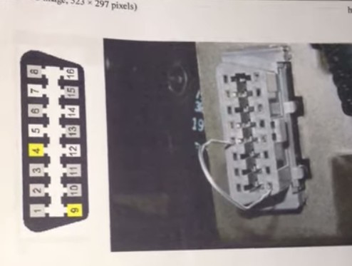
The On-Board Diagnostics II (OBD2) port in your vehicle is a crucial interface for accessing valuable data about your car’s health and performance. For automotive technicians and DIY enthusiasts alike, understanding the function of each pin within this port is essential for accurate diagnostics and repairs. While many focus on the data communication pins, the ground pins, specifically pin 4 and pin 9, are equally important for ensuring a stable and reliable connection with diagnostic tools.
Pin 4 and pin 9 on the OBD2 connector are designated as ground pins, but they serve slightly different purposes. Pin 4 is the Chassis Ground, and Pin 5 is Signal Ground. Although the original poster in the linked forum experienced issues by mistakenly shorting Pin 5 (Signal Ground) and Pin 16 (+12V Battery), understanding the role of Pin 4 and Pin 9 as ground connections is fundamental for anyone working with OBD2 systems.
 OBD2 Connector Pinout Diagram Correctly Showing Pin 4 and 9 as Ground
Why are Ground Pins Important?
Ground pins provide a common reference point for electrical circuits within the vehicle and the diagnostic tools connected to the OBD2 port. Without proper grounding, communication signals can become distorted or unreliable, leading to inaccurate diagnostic readings or even damage to electronic components.
-
Pin 4 – Chassis Ground: This pin is typically connected directly to the vehicle’s chassis, providing a solid and stable ground reference. It is crucial for ensuring that the diagnostic tool and the vehicle’s electronic control units (ECUs) share the same ground potential. This minimizes electrical noise and ensures accurate signal transmission.
-
Pin 9 – Signal Ground (though Pin 5 is more commonly Signal Ground): While some sources may list Pin 9 as Signal Ground, Pin 5 is more commonly designated as Signal Ground in most OBD2 pinout standards. Signal ground is intended to provide a clean ground reference specifically for the sensitive electronic signals used in data communication. It is designed to be less noisy than chassis ground, further improving the reliability of data transfer between the diagnostic tool and the vehicle’s systems. In some vehicle implementations, Pin 9 might be manufacturer-discretionary or used for specific communication protocols, so always refer to the vehicle-specific wiring diagrams for definitive information.
Potential Issues Related to Ground Pins
While the original forum post detailed a mistake with Pin 5 and Pin 16, problems with ground pins (Pin 4 and, less commonly in standard OBD2, Pin 9 if it were to be used as signal ground) can also lead to diagnostic issues:
-
Poor Connection: Corrosion, loose connections, or damage to the ground pins can disrupt the ground circuit. This can result in intermittent or no communication with the diagnostic tool. Symptoms might include:
- OBD2 scanner failing to power on when connected to the port.
- Inability to establish a communication link with the vehicle’s ECUs.
- Erratic or unreliable diagnostic data.
-
Ground Loops: Although less directly related to Pin 4 and 9 themselves, issues in the vehicle’s overall grounding system can affect the OBD2 port’s ground reference. Ground loops can introduce noise into the system, potentially disrupting diagnostics.
-
Short Circuits (Indirectly Related): As demonstrated in the original post, mistakenly shorting a power pin to a ground pin (even if it was Pin 5 in that case) highlights the dangers of incorrect probing or jumpering of the OBD2 port. While Pin 4 and 9 are ground pins, accidentally shorting them to other pins, especially power pins, could still cause electrical problems, although less likely to be directly damaging compared to shorting power to signal ground as in the original example.
Troubleshooting OBD2 Ground Pin Issues
If you are experiencing problems connecting to your vehicle’s OBD2 port, or suspect ground-related issues, here are some troubleshooting steps:
- Visual Inspection: Carefully inspect the OBD2 port for any signs of corrosion, bent pins, or damage, particularly around pins 4 and 9.
- Continuity Test: Use a multimeter to check the continuity between Pin 4 and a known good chassis ground point on the vehicle. Similarly, check continuity for Pin 5 (or Pin 9 if documented as signal ground for that vehicle) to other signal ground points if schematics are available.
- Voltage Drop Test: Under load (while the diagnostic tool is connected and attempting to communicate), measure the voltage drop between Pin 4 and chassis ground. Excessive voltage drop indicates a poor ground connection.
- Consult Wiring Diagrams: Refer to the vehicle’s wiring diagrams to understand the specific grounding configuration for the OBD2 port and identify any other relevant ground points in the system.
Conclusion
While the original post serves as a cautionary tale about the risks of misidentifying OBD2 pins, it also underscores the importance of understanding the fundamental functions of each pin, including the ground connections at Pin 4 and Pin 9 (and Pin 5). Properly functioning ground circuits are essential for reliable OBD2 diagnostics. By understanding the roles of chassis ground and signal ground, and by following basic troubleshooting steps, technicians and DIYers can ensure accurate and safe interaction with their vehicle’s diagnostic systems. Always double-check pinouts and consult vehicle-specific repair information before performing any tests or procedures on the OBD2 port.
