The world of On-Board Diagnostics II (OBD2) is essential for modern automotive repair and diagnostics. Within the OBD2 standard, a variety of communication protocols exist, each with its own specifications and applications. This article delves into one such protocol: SAE J1850 PWM (Pulse Width Modulation), commonly associated with Ford vehicles. Understanding SAE J1850 PWM is crucial for anyone working with OBD2 systems, especially when dealing with Ford models.
What is SAE J1850 PWM?
SAE J1850 PWM is one of the five primary OBD2 communication protocols. It utilizes Pulse Width Modulation (PWM) to transmit data between a vehicle’s Electronic Control Units (ECUs) and an external diagnostic tool. PWM is a technique where the width of a pulse is varied to represent the data being transmitted. In the case of SAE J1850 PWM, this signal operates at a speed of 41.6 kbps. This protocol was predominantly adopted by Ford in their vehicles, making it a key protocol to understand when diagnosing Ford cars and trucks.
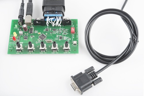 Automotive ECU for diagnostics and repair
Depiction of an Automotive Electronic Control Unit (ECU) commonly accessed via OBD2 for diagnostics and repair procedures.
SAE J1850 PWM: Pin Configuration and Technical Details
To interface with a vehicle using SAE J1850 PWM, you need to understand which pins on the Diagnostic Link Connector (DLC) are used by this protocol. The OBD2 DLC is a standardized 16-pin connector, and for SAE J1850 PWM, the following pins are relevant:
| Feature | Description |
|---|---|
| BUS + | Pin 2 |
| BUS – | Pin 10 |
| 12V Power | Pin 16 (Provides power to the diagnostic tool) |
| Ground (GND) | Pins 4, 5 (Ground connections) |
| Bus State | Active when BUS + is HIGH, BUS – is LOW |
| Maximum Voltage | 5V |
| Minimum Voltage | 0V |
| Data Byte Size | 12 bytes |
| Bit Timing (‘1’ bit) | 8µS (microseconds) |
| Bit Timing (‘0’ bit) | 16µS (microseconds) |
| Start of Frame | 48µS (microseconds) |
Key Characteristics of SAE J1850 PWM:
- Differential Bus: SAE J1850 PWM uses a differential bus, indicated by the BUS+ and BUS- pins. This differential signaling method improves noise immunity, making communication more reliable in the electrically noisy automotive environment.
- Active Bus State: The bus is considered active when the BUS+ line is pulled HIGH (5V) and the BUS- line is pulled LOW (0V).
- Data Transmission: Data is transmitted using pulse width modulation at 41.6 kbps. The varying width of the pulses encodes the binary data.
- Ford Dominance: While other protocols exist within OBD2, SAE J1850 PWM is strongly associated with Ford vehicles, particularly older models. It’s essential to check vehicle specifications to confirm protocol usage.
SAE J1850 PWM vs. Other OBD2 Protocols
While SAE J1850 PWM was prominent, other OBD2 protocols exist, each with its own characteristics and manufacturer preferences. These include:
- SAE J1850 VPW (Variable Pulse Width): Used by GM, operates at 10.4 kbps, and also uses Pin 2 for BUS+.
- ISO 9141-2: Common in Chrysler, European, and Asian vehicles, using asynchronous serial communication at 10.4 kbps via the K-line (Pin 7).
- ISO 14230 KWP2000 (Keyword Protocol 2000): Also asynchronous serial communication at 10.4 kbps, similar vehicle applications as ISO 9141-2, utilizing the K-line (Pin 7).
- ISO 15765 CAN (Controller Area Network): Mandatory in US vehicles since 2008 and widely used in European cars from 2003 onwards. CAN is a high-speed protocol (up to 1 Mbps) using CAN High (Pin 6) and CAN Low (Pin 14).
Understanding these different protocols is vital for effective OBD2 diagnostics. Scan tools often need to be compatible with multiple protocols to cover a wide range of vehicles.
Conclusion
SAE J1850 PWM is a significant OBD2 protocol, particularly for diagnosing Ford vehicles. Its use of Pulse Width Modulation and specific pin assignments on the DLC are important for technicians and DIY enthusiasts to understand. While modern vehicles increasingly use CAN, knowledge of SAE J1850 PWM remains valuable for working with older Ford models and appreciating the evolution of automotive diagnostic communication. When working with OBD2 systems, always verify the vehicle’s protocol to ensure proper communication and accurate diagnostics.