Need a straightforward and detailed understanding of OBD2 and its services?
This guide provides an in-depth exploration of the On-Board Diagnostics version 2 (OBD2) protocol, including the OBD2 connector, OBD2 Parameter IDs (PIDs), and its connection to the Controller Area Network (CAN) bus.
Note: This is designed to be a comprehensive guide, offering you practical knowledge on how to request and interpret OBD2 data, explore key applications, and gain valuable insights.
Discover why this is becoming a leading resource for understanding Obd2 Services.
You can also explore our introductory video on OBD2 above or download the PDF version for offline reading.
Article Contents:
Author: Martin Falch (Updated January 2025)
Download this guide as a PDF
Decoding OBD2: What Are OBD2 Services?
OBD2, or On-Board Diagnostics II, is essentially your vehicle’s internal health monitoring system. It’s a standardized protocol that allows access to crucial diagnostic information, including diagnostic trouble codes (DTCs) and real-time vehicle data, all accessible through the OBD2 connector. Understanding OBD2 services begins with recognizing its role in modern vehicle maintenance and diagnostics.
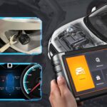
You’ve likely already encountered OBD2 in action without realizing it. That check engine light, officially known as the malfunction indicator light, on your dashboard? That’s your car’s OBD2 system flagging a potential problem. When you take your car to a mechanic, they use an OBD2 scanner as a primary tool to diagnose these issues. These scanners are essential for accessing OBD2 services.
To perform a diagnosis, a mechanic connects an OBD2 reader to the standard 16-pin OBD2 connector, typically located near the steering wheel. This tool sends ‘OBD2 requests’ to the vehicle’s computer system, and the car responds with ‘OBD2 responses’. These responses can contain a wealth of information, from vehicle speed and fuel level to detailed Diagnostic Trouble Codes (DTCs). This communication forms the basis of OBD2 services, enabling quicker and more accurate troubleshooting.
Alt text: Understanding OBD2 services and the Malfunction Indicator Light (MIL) on a car dashboard, highlighting the use of an OBD2 scan tool for diagnostics.
OBD2 Compatibility: Is Your Car Supported?
The question of OBD2 compatibility is simple for most modern vehicles: Almost certainly, yes!
Nearly all contemporary non-electric cars are equipped with OBD2 systems, and the majority communicate using the CAN bus protocol. However, for older vehicles, the presence of a 16-pin OBD2 connector doesn’t guarantee full OBD2 support. Some may have the connector but not implement the full OBD2 protocol. A key indicator of compliance is the vehicle’s market and year of manufacture:
Alt text: OBD2 compatibility chart by region and year, illustrating when OBD2 became mandatory in the EU and US for different vehicle types, crucial for accessing OBD2 services.
A Look at OBD2 History
The origins of OBD2 can be traced back to California, where the California Air Resources Board (CARB) mandated On-Board Diagnostics (OBD) in all new cars starting from 1991 to monitor and control vehicle emissions. This was the initial step towards standardized OBD2 services.
The OBD2 standard itself was developed and recommended by the Society of Automotive Engineers (SAE), leading to the standardization of DTCs and the OBD connector across different vehicle manufacturers through the SAE J1962 standard. This standardization was vital for making OBD2 services universally accessible.
The rollout of the OBD2 standard was phased and progressive:
- 1996: OBD2 became mandatory in the USA for all cars and light trucks.
- 2001: The European Union mandated OBD2 for gasoline cars.
- 2003: The EU extended the mandate to include diesel cars (known as EOBD in Europe).
- 2005: OBD2 compliance was required in the US for medium-duty vehicles.
- 2008: US vehicles were required to adopt ISO 15765-4 (CAN) as the foundation for OBD2 communication.
- 2010: Finally, OBD2 became mandatory in the US for heavy-duty vehicles, completing its implementation across vehicle categories.
Alt text: OBD2 history infographic showing the evolution of emission control standards and the role of OBD2 and EOBD in automotive diagnostics, highlighting the growing importance of OBD2 services.
Alt text: Timeline of OBD2 history, detailing key milestones in the standardization and mandatory implementation of OBD2 and related diagnostic services across different years and regions.
Alt text: Conceptual image of OBD3 future trends, depicting remote diagnostics, emissions testing, cloud connectivity, and IoT integration for advanced OBD2 services.
The Future of OBD2: Trends and Innovations in OBD2 Services
OBD2 is firmly established, but its evolution continues. The landscape of OBD2 services is being shaped by several key trends.
Initially conceived for emissions monitoring and control, legislated OBD2 is not strictly required for electric vehicles (EVs). Consequently, most modern EVs do not fully support standard OBD2 requests. Instead, they often utilize OEM-specific Unified Diagnostic Services (UDS) for communication. This shift makes accessing data from EVs challenging unless decoding methods are reverse-engineered. However, there are successful case studies in decoding data from EVs like Tesla, Hyundai/Kia, Nissan, and VW/Skoda, demonstrating the evolving landscape of OBD2 services in the electric vehicle sector.
Current OBD2 implementations face limitations in data richness and underlying communication protocols. In response, advanced alternatives like WWH-OBD (World Wide Harmonized OBD) and OBDonUDS (OBD on UDS) have emerged. These protocols aim to improve OBD communication by using the UDS protocol as a base, promising enhanced OBD2 services in the future. For deeper insights into these protocols, our introduction to UDS provides further details.
In our increasingly connected world, traditional OBD2 testing methods can seem outdated. Manual emission checks are time-intensive and costly. The proposed solution is OBD3 – integrating telematics into all vehicles.
OBD3 envisions adding a small radio transponder to all cars, similar to those used for electronic toll collection. This technology would allow for wireless transmission of the car’s Vehicle Identification Number (VIN) and DTCs to a central server for automated checks via WiFi. Devices like the CANedge2 WiFi CAN logger and the CANedge3 3G/4G CAN logger already facilitate CAN or OBD2 data transfer over WiFi/cellular networks. While offering cost savings and convenience, OBD3 raises political and privacy concerns related to increased vehicle surveillance. The evolution towards OBD3 will significantly impact the delivery of OBD2 services.
Originally designed for stationary emission inspections, OBD2 is now extensively used by third parties for real-time data generation via OBD2 dongles, CAN loggers and similar tools. However, the German automotive industry is exploring changes that could limit this third-party access.
A proposal suggests deactivating OBD2 functionality during driving, centralizing data collection with manufacturers. This would give manufacturers greater control over ‘automotive big data’. Arguments for this shift include enhanced security, aiming to mitigate the risk of car hacking. However, many perceive this as a commercially motivated move to control the aftermarket for OBD2 services and data. The future of third-party OBD2 services remains uncertain as these trends develop.
Alt text: Visual representation of the future of OBD2 services and electric vehicles, depicting an OBD2 connector being removed from an EV, symbolizing potential challenges in data access and diagnostic services for EVs.
Expand Your Expertise with our ‘Ultimate CAN Guide’
Aiming to become a CAN bus expert and deepen your understanding of OBD2 services?
Our comprehensive 160+ page PDF combines 12 ‘simple introductions’ into one resource:
Download the Ultimate CAN Guide Now
Alt text: Cover image of the “CAN Bus – The Ultimate Guide Tutorial PDF”, promoting in-depth learning about CAN bus and related OBD2 services and technologies.
OBD2 Standards: Defining the Framework for OBD2 Services
On-board diagnostics, specifically OBD2, operates as a higher-layer protocol, similar to a language, while CAN serves as the communication method, analogous to a telephone line. This positions OBD2 alongside other CAN-based higher-layer protocols such as J1939, CANopen, and NMEA 2000. Understanding these standards is key to effectively utilizing OBD2 services.
OBD2 standards comprehensively define the OBD2 connector, the underlying lower-layer protocols, OBD2 Parameter IDs (PIDs), and other critical aspects of the system. These standards ensure consistency and interoperability in OBD2 services across different manufacturers and tools.
These standards can be organized using the 7-layer OSI model, highlighting the layered approach to communication. Notably, both SAE and ISO standards contribute to various layers. This reflects the development of OBD standards in both the USA (SAE) and Europe (ISO). Many of these standards are technically very similar, for example, SAE J1979 is nearly equivalent to ISO 15031-5, and SAE J1962 closely mirrors ISO 15031-3. Adherence to these standards is crucial for reliable OBD2 services.
Alt text: OSI Model diagram comparing OBD2 and CAN bus, illustrating the ISO 15765 and ISO 11898 standards across the 7-layer model and their relevance to OBD2 services.
Alt text: OBD2 connector pinout diagram, showing a Type A female socket and Data Link Connector (DLC) configuration, essential for understanding physical connections for OBD2 services.
The OBD2 Connector: SAE J1962 Standard for Physical OBD2 Services
The 16-pin OBD2 connector is the physical interface that allows you to easily retrieve data from your vehicle. It is rigorously defined by the SAE J1962 / ISO 15031-3 standard. This connector is the gateway to accessing OBD2 services.
The illustration above shows a typical Type A OBD2 pin connector, also known as the Data Link Connector (DLC). Key points about the OBD2 connector include:
- Location: Usually found near the steering wheel, though sometimes it may be hidden from immediate view.
- Pin 16: Supplies battery power, often even when the ignition is off, allowing for continuous OBD2 services like data logging.
- Pinout Variation: The specific OBD2 pinout configuration depends on the communication protocol used by the vehicle.
- CAN Bus Dominance: The most prevalent lower-layer protocol is CAN bus, meaning pins 6 (CAN-H) and 14 (CAN-L) are commonly used for communication, facilitating CAN-based OBD2 services.
OBD2 Connector Types: A vs. B for Different OBD2 Services
In practice, you might encounter both Type A and Type B OBD2 connectors. Type A is predominantly used in cars and light-duty vehicles, while Type B is more common in medium and heavy-duty vehicles. Understanding the difference is important for selecting the correct equipment for OBD2 services.
As shown in the illustration, both types share similar OBD2 pinouts but differ in power supply outputs: Type A typically provides 12V, while Type B provides 24V. Baud rates can also vary, with cars generally using 500K and heavy-duty vehicles often using 250K (though 500K support is increasing). These variations impact the compatibility and performance of OBD2 services.
Visually distinguishing between the two types is straightforward: the Type B OBD2 connector has a distinct interrupted groove in the middle. Consequently, a Type B OBD2 adapter cable is universally compatible with both Type A and Type B sockets, whereas a Type A adapter will only fit into Type A sockets. This compatibility consideration is crucial for anyone working with OBD2 services across different vehicle types.
Alt text: Comparison of OBD2 Connector Type A and Type B as per SAE J1962, highlighting differences in 12V and 24V power supply and application in cars, vans, and trucks for various OBD2 services.
Alt text: Diagram contrasting OBD2 and CAN bus within the ISO15765 framework, illustrating their relationship and how they enable communication for OBD2 services.
OBD2 and CAN Bus: ISO 15765-4 – The Backbone of Modern OBD2 Services
Since 2008, CAN bus has been mandated as the primary lower-layer protocol for OBD2 in all vehicles sold in the US, as per ISO 15765. This standardization has significantly shaped the delivery of OBD2 services.
ISO 15765-4, also known as Diagnostics over CAN (DoCAN), specifies a set of constraints and guidelines applied to the CAN standard (ISO 11898). It standardizes the CAN interface for diagnostic equipment, focusing on the physical, data link, and network layers. Key specifications for CAN-based OBD2 services include:
- Bit-rate: Must be either 250K or 500K.
- CAN IDs: Can be either 11-bit or 29-bit.
- Specific CAN IDs: Reserved for OBD requests and responses to ensure proper routing of OBD2 services communication.
- Data Frame Length: Diagnostic CAN frames must have a data length of 8 bytes.
- Adapter Cable Length: OBD2 adapter cables are limited to a maximum length of 5 meters to maintain signal integrity for reliable OBD2 services.
OBD2 CAN Identifiers: 11-bit and 29-bit Addressing in OBD2 Services
All OBD2 communication is structured around request and response message pairs. These messages are fundamental to accessing OBD2 services.
In most passenger cars, 11-bit CAN IDs are used for OBD2 communication. The ‘Functional Addressing’ ID is 0x7DF, used to query all OBD2-compatible Electronic Control Units (ECUs) to check if they have data to report for the requested parameter, as defined in ISO 15765-4. Alternatively, CAN IDs in the range 0x7E0-0x7E7 can be used for ‘Physical Addressing’ requests to specific ECUs, although this is less commonly used in standard OBD2 services.
ECUs respond using 11-bit IDs in the range 0x7E8-0x7EF. The most common response ID is 0x7E8, typically from the Engine Control Module (ECM), with 0x7E9 from the Transmission Control Module (TCM) also being frequently seen. These response IDs are crucial for interpreting data within OBD2 services.
In some vehicles, particularly vans and medium to heavy-duty vehicles, extended 29-bit CAN identifiers may be used for OBD2 communication instead of the standard 11-bit IDs.
For 29-bit IDs, the ‘Functional Addressing’ CAN ID is 0x18DB33F1.
Responses in 29-bit systems are typically found with CAN IDs ranging from 0x18DAF100 to 0x18DAF1FF, commonly 0x18DAF110 and 0x18DAF11E. This response ID is sometimes represented in the ‘J1939 PGN’ format, specifically PGN 0xDA00 (55808), which the J1939-71 standard designates as ‘Reserved for ISO 15765-2’. Understanding these identifiers is essential for diagnosing and utilizing OBD2 services effectively.
Alt text: Diagram illustrating OBD2 protocol request and response frames, showing the flow of data and parameters in OBD2 communication for diagnostic services.
Alt text: Table overview of OBD2 CAN bus identifiers, including 7DF, 7E8, and 7E0, explaining their roles in functional and physical addressing within OBD2 services.
Alt text: Diagram contrasting OBD2 and proprietary CAN bus protocols, highlighting the differences in data access and standardization for vehicle diagnostics and OBD2 services.
OBD2 vs. Proprietary CAN Protocols: Expanding Beyond Standard OBD2 Services
It’s crucial to understand that your vehicle’s Electronic Control Units (ECUs) operate using proprietary CAN protocols developed by the Original Equipment Manufacturer (OEM), independently of OBD2. These proprietary protocols are often specific to the vehicle’s brand, model, and year, and are essential for the core functions of the vehicle. These OEM protocols operate in parallel with OBD2 services.
Unless you are the OEM, interpreting this proprietary CAN data is generally not possible without reverse engineering. However, connecting a CAN bus data logger to your vehicle’s OBD2 connector may allow you to observe OEM-specific CAN data, typically broadcast at high rates of 1000-2000 frames per second. In many newer vehicles, a ‘gateway’ system blocks access to this proprietary CAN data through the OBD2 connector, restricting access to standard OBD2 services.
In essence, OBD2 should be viewed as an ‘extra’ higher-layer protocol that operates alongside the OEM-specific protocol. It provides a standardized interface for diagnostics and emissions-related data, while the OEM protocol manages the vehicle’s core operations. This distinction is important for understanding the scope and limitations of OBD2 services.
Bit-rate and ID Validation: Ensuring Correct Communication for OBD2 Services
As previously mentioned, OBD2 can utilize two different bit-rates (250K, 500K) and two CAN ID lengths (11-bit, 29-bit), resulting in four potential communication configurations. Modern vehicles commonly use 500K with 11-bit IDs, but diagnostic tools must systematically verify these parameters to ensure proper communication and access to OBD2 services.
ISO 15765-4 provides guidelines for a systematic initialization sequence to determine the correct configuration. This process relies on the fact that OBD2-compliant vehicles must respond to a specific mandatory OBD2 request (detailed in the OBD2 PID section) and that using an incorrect bit-rate will result in CAN error frames. Correct bit-rate and ID validation is fundamental for reliable OBD2 services.
Newer versions of ISO 15765-4 account for vehicles that may support OBD communication via OBDonUDS rather than the traditional OBDonEDS. While this article primarily focuses on OBD2/OBDonEDS (OBD on Emission Diagnostic Service as per ISO 15031-5/SAE J1979), it’s important to note the emergence of WWH-OBD/OBDonUDS (OBD on Unified Diagnostic Service as per ISO 14229, ISO 27145-3/SAE J1979-2), especially in EU trucks and buses. The choice between OBDonEDS and OBDonUDS impacts the implementation and capabilities of OBD2 services.
To test for the ‘protocol’ type—OBDonEDS versus OBDonUDS—diagnostic tools may include additional request messages, specifically sending UDS requests with 11-bit/29-bit functional address IDs for service 0x22 and data identifier (DID) 0xF810 (protocol identification). Vehicles supporting OBDonUDS must have ECUs that respond to this DID.
Currently, OBDonEDS (also known as OBD2, SAE OBD, EOBD, or ISO OBD) is prevalent in most non-EV vehicles, while WWH-OBD is primarily used in European trucks and buses. Understanding these protocol variations is key to effectively deploying OBD2 services across different vehicle types and regions.
Alt text: Flowchart of OBD2 bit-rate and CAN ID validation process according to ISO 15765-4, outlining steps for ensuring correct communication parameters for OBD2 services.
Alt text: Diagram illustrating the five lower-layer OBD2 protocols: CAN (ISO 15765), KWP2000 (ISO14230-4), SAE J1850 (VPW & PWM), and ISO 9141, showing the evolution of communication methods for OBD2 services.
Five Lower-Layer OBD2 Protocols: Historical Context for OBD2 Services
CAN bus, as per ISO 15765, is the dominant lower-layer protocol for OBD2 in modern vehicles. However, when working with older vehicles (pre-2008), it’s important to be aware of the other four lower-layer protocols that were previously used as foundations for OBD2. The OBD2 connector pinouts can sometimes indicate which protocol is in use. Understanding these historical protocols provides context for the evolution of OBD2 services.
The five lower-layer protocols include:
- ISO 15765 (CAN bus): Mandatory in US vehicles since 2008 and now the most widely used protocol for OBD2 services.
- ISO14230-4 (KWP2000): Keyword Protocol 2000, common in 2003+ vehicles, especially in Asia, for implementing OBD2 services.
- ISO 9141-2: Used in European, Chrysler, and Asian vehicles around 2000-2004 for early OBD2 services.
- SAE J1850 (VPW – Variable Pulse Width): Predominantly used in older General Motors (GM) vehicles.
- SAE J1850 (PWM – Pulse Width Modulation): Mainly used in older Ford vehicles.
Transporting OBD2 Messages via ISO-TP: Handling Larger Data in OBD2 Services
All OBD2 data is transmitted over the CAN bus using the ISO-TP (ISO 15765-2) transport protocol. This protocol is essential because it enables the communication of data payloads larger than the 8-byte limit of a standard CAN frame. ISO-TP is crucial for OBD2 services that require transmitting more than 8 bytes of data at once.
ISO-TP becomes necessary in OBD2, for example, when retrieving the Vehicle Identification Number (VIN) or Diagnostic Trouble Codes (DTCs), which often exceed 8 bytes. ISO 15765-2 provides mechanisms for segmentation, flow control, and reassembly of these larger messages, ensuring reliable transmission for comprehensive OBD2 services. For a more detailed explanation, refer to our introduction to UDS.
However, many OBD2 data transmissions are small enough to fit within a single CAN frame. In these cases, ISO 15765-2 specifies the use of a ‘Single Frame’ (SF) format. In a Single Frame, the first data byte (known as the PCI field) indicates the payload length (excluding padding), leaving up to 7 bytes for the actual OBD2 communication. This efficient use of single frames optimizes communication for many common OBD2 services.
Alt text: Diagram of ISO 15765-2 ISO-TP OBD2 frame types, illustrating Single Frame, First Frame, Consecutive Frame, and Flow Control frames and their roles in OBD2 services data transmission.
The OBD2 Diagnostic Message: Structure of Communication for OBD2 Services
To better understand how OBD2 functions over CAN, let’s examine the structure of a raw ‘Single Frame’ OBD2 CAN message. In simple terms, an OBD2 message consists of a CAN identifier, a data length indicator (PCI field), and the data payload itself. The data portion is further divided into Mode, Parameter ID (PID), and data bytes. This structured message format is fundamental to all OBD2 services.
Alt text: Breakdown of an OBD2 message structure, explaining the components of a raw OBD2 frame including Mode, PID, Identifier, and Data Bytes, essential for understanding OBD2 services communication.
Example: OBD2 Request/Response Sequence for OBD2 Services
Before diving into the details of each part of the OBD2 message, consider a practical example: requesting and receiving vehicle speed data. This example illustrates a typical OBD2 service interaction.
In this scenario, an external diagnostic tool sends a request message to the vehicle. This message uses CAN ID 0x7DF and includes 2 payload bytes: Mode 0x01 and PID 0x0D. The vehicle’s ECU, in response, transmits a message using CAN ID 0x7E8. This response contains 3 payload bytes, with the vehicle speed value encoded in the 4th byte as 0x32 (which is 50 in decimal). This exchange is a basic example of how OBD2 services operate.
By consulting the decoding rules for OBD2 PID 0x0D, we can determine that the hexadecimal value 0x32 corresponds to a physical vehicle speed of 50 km/h. This process of request and response, combined with PID decoding, is central to utilizing OBD2 services for vehicle diagnostics and data retrieval.
Alt text: Example of an OBD2 request and response sequence using CAN IDs 7DF and 7E8, specifically for retrieving vehicle speed data, showcasing a fundamental OBD2 service interaction.
Alt text: Detailed example of OBD2 PID 0D for vehicle speed, explaining the hexadecimal to physical value conversion and data interpretation within OBD2 services.
Alt text: Overview of the 10 OBD2 service modes, including modes for current data, freeze frame, and clearing DTCs, providing a summary of available diagnostic functionalities in OBD2 services.
The 10 OBD2 Services (Modes): Categorizing OBD2 Services Functionality
There are ten standardized OBD2 diagnostic services, commonly referred to as modes. Each mode is designed for a specific diagnostic purpose, collectively providing a comprehensive suite of OBD2 services. Mode 0x01 is used to access current, real-time vehicle data, while other modes are used to retrieve and clear Diagnostic Trouble Codes (DTCs), or to access freeze frame data captured when a DTC was set. These modes categorize the different types of OBD2 services available.
It is important to note that vehicles are not required to support all ten OBD2 modes. Moreover, manufacturers may implement additional, OEM-specific OBD2 modes beyond these ten standard modes, expanding the range of OBD2 services that can be accessed.
In OBD2 messages, the service mode is indicated in the second byte of the data payload. In a request message, the mode is included directly (e.g., 0x01). In a response message, 0x40 is added to the requested mode (e.g., a response to mode 0x01 will start with 0x41). This mode identification is crucial for correctly interpreting OBD2 services responses.
OBD2 Parameter IDs (PIDs): Accessing Specific Data Points in OBD2 Services
Within each OBD2 service mode, Parameter IDs (PIDs) are used to specify particular data points or parameters of interest. PIDs are essential for requesting and receiving specific information through OBD2 services.
For example, within mode 0x01 (Show current data), there are approximately 200 standardized PIDs defined. These PIDs cover a wide range of real-time data, including vehicle speed, engine RPM, and fuel level. However, a vehicle does not need to support all defined PIDs within a given mode. In practice, most vehicles support only a subset of the available PIDs. The supported PIDs vary depending on the vehicle manufacturer and model, affecting the scope of OBD2 services available.
In this context, one PID is particularly significant: Mode 0x01 PID 0x00. If an emissions-related ECU supports any OBD2 services at all, it is mandatory for it to support mode 0x01 PID 0x00. When this PID is requested, the vehicle ECU responds by indicating which PIDs in the range 0x01-0x20 it supports. This makes PID 0x00 a fundamental tool for OBD2 compatibility testing. Additionally, PIDs 0x20, 0x40, 0x60, 0x80, 0xA0, and 0xC0 are used to determine support for subsequent ranges of mode 0x01 PIDs, allowing for a comprehensive assessment of OBD2 services support.
Alt text: Diagram illustrating OBD2 protocol request and response frames again, emphasizing the role of PIDs in specifying data parameters within OBD2 services communication.
Alt text: Screenshot of an OBD2 PID overview tool, showing service 01 and its functionalities for exploring and utilizing OBD2 services and data parameters.
Tip: OBD2 PID Overview Tool for Efficient OBD2 Services Usage
The appendices of SAE J1979 and ISO 15031-5 contain detailed scaling information for standard OBD2 PIDs. This information is essential for decoding the raw data received from OBD2 services into meaningful physical values, as explained in our CAN bus introduction.
If you need to quickly look up a mode 0x01 PID, our OBD2 PID overview tool is an invaluable resource. This tool assists in constructing OBD2 request frames and dynamically decodes OBD2 responses, streamlining the use of OBD2 services.
Access the OBD2 PID overview tool here
Practical Guide: Logging and Decoding OBD2 Data for OBD2 Services
This section provides a practical example of how to log OBD2 data using the CANedge CAN bus data logger. This hands-on guide demonstrates the real-world application of OBD2 services.
The CANedge is configurable to transmit custom CAN frames, making it ideal for OBD2 logging. This capability allows users to tailor OBD2 services data collection to their specific needs.
Once configured, the CANedge can be easily connected to your vehicle using our OBD2-DB9 adapter cable. This setup provides a straightforward way to access and utilize OBD2 services for data logging and analysis.
Alt text: Diagram illustrating OBD2 PID data logging with a data logger, showing request and response CAN IDs 7DF and 7E8 in the context of OBD2 services data acquisition.
Example of bit-rate validation for OBD2 communication.
Alt text: Screenshot showing bit-rate validation for OBD2, demonstrating a step in setting up reliable communication for accessing OBD2 services.
Example of reviewing supported PIDs using asammdf software.
Alt text: Screenshot from asammdf software showing OBD2 supported PID test responses, illustrating the process of identifying available OBD2 services parameters.
Alt text: Screenshot of an OBD2 PID lookup tool displaying supported PIDs, demonstrating how to decode and interpret OBD2 services capabilities.
Step #1: Testing Bit-rate, IDs, and Supported PIDs for Effective OBD2 Services
As discussed earlier, ISO 15765-4 outlines a procedure to determine the correct bit-rate and CAN IDs for a specific vehicle. You can perform these tests using the CANedge as follows (refer to the CANedge Introduction for detailed instructions): These initial tests are crucial for ensuring proper access to OBD2 services.
- Bit-rate Test: Send a CAN frame at 500K bit-rate and check for successful transmission. If unsuccessful, repeat at 250K.
- Bit-rate Configuration: Use the identified bit-rate for all subsequent OBD2 communication.
- Supported PIDs Request: Send multiple ‘Supported PIDs’ requests (using mode 0x01 PID 0x00) and analyze the responses.
- ID Type Determination: Based on the response IDs (0x7E8-0x7EF for 11-bit, 0x18DAF1xx for 29-bit), determine whether the vehicle uses 11-bit or 29-bit CAN IDs for OBD2 services.
- PID Support Identification: Analyze the response data to determine which PIDs are supported by the vehicle’s ECUs, defining the scope of available OBD2 services.
We provide ready-to-use configuration files to simplify these initial tests, making it easier to set up your system for OBD2 services data logging.
Most non-EV vehicles manufactured in 2008 or later typically support 40-80 PIDs using a 500K bit-rate, 11-bit CAN IDs, and the OBD2/OBDonEDS protocol. Understanding these common parameters is helpful for effectively utilizing OBD2 services.
As illustrated in the asammdf GUI screenshot, it’s common to receive multiple responses to a single OBD request when using the functional address ID 0x7DF, as this ID polls all ECUs for a response. Since all OBD2/OBDonEDS-compliant ECUs must support service 0x01 PID 0x00, there are often numerous responses to this particular PID. For subsequent ‘Supported PIDs’ requests, fewer ECUs typically respond. Notably, the ECM ECU (0x7E8) often supports all PIDs supported by other ECUs in the vehicle. To reduce bus load, especially in scenarios with many ECUs, you can switch to ‘Physical Addressing’ by using CAN ID 0x7E0 for subsequent communication, directing requests specifically to the ECM for more efficient OBD2 services data retrieval.
Step #2: Configuring OBD2 PID Requests for Targeted OBD2 Services
Once you have identified the OBD2 PIDs supported by your vehicle and determined the correct bit-rate and CAN IDs, you can proceed to configure your data logger to request specific PIDs of interest. This step allows you to tailor your OBD2 services data logging to your specific needs.
When configuring PID requests, consider these points:
- CAN IDs: Shift to ‘Physical Addressing’ request IDs (e.g., 0x7E0) to target specific ECUs and avoid redundant responses, optimizing OBD2 services data collection.
- Spacing: Introduce a delay of 300-500 ms between each OBD2 request. Sending requests too rapidly may overwhelm the ECUs and result in missed responses. Proper spacing ensures reliable OBD2 services communication.
- Battery Drain: Utilize triggers to stop PID requests when the vehicle is inactive. This prevents unnecessary battery drain and avoids ‘waking up’ ECUs when data logging is not required, conserving power during OBD2 services use.
- Filters: Implement filters to record only OBD2 responses. If your vehicle also broadcasts OEM-specific CAN data, filters help to isolate the relevant OBD2 data, streamlining OBD2 services data analysis.
With these configurations in place, your CANedge is ready to log raw OBD2 data efficiently and effectively, providing valuable insights through OBD2 services.
Example configuration of an OBD2 PID request transmit list for CANedge.
Alt text: Example CANedge OBD2 PID request transmit list configuration, showing how to set up specific PID requests for targeted OBD2 services data logging.
Visualization of decoded OBD2 data in asammdf.
Alt text: Visual plot of decoded OBD2 data using asammdf software and a CAN bus DBC file, illustrating data visualization and analysis capabilities for OBD2 services outputs.
Step #3: DBC Decoding of Raw OBD2 Data for Usable OBD2 Services Output
To effectively analyze and visualize the logged raw OBD2 data, you need to decode it into physical values, such as kilometers per hour (km/h) or degrees Celsius (°C). This decoding process is crucial for transforming raw data into actionable insights from OBD2 services.
The necessary decoding information is specified in ISO 15031-5/SAE J1979 and is also often available on resources like Wikipedia. For your convenience, we offer a free OBD2 DBC file that simplifies the process of DBC decoding raw OBD2 data in most CAN bus software tools. This DBC file streamlines the interpretation of OBD2 services data.
Decoding OBD2 data is somewhat more complex than decoding standard CAN signals. This complexity arises because different OBD2 PIDs are transmitted using the same CAN ID (e.g., 0x7E8). Therefore, the CAN ID alone is not sufficient to uniquely identify the signals encoded in the payload. This multiplexing requires a more sophisticated approach to data interpretation for OBD2 services.
To overcome this, you must consider not only the CAN ID but also the OBD2 mode and OBD2 PID to accurately identify each signal. This technique is known as ‘extended multiplexing‘ and can be effectively implemented using DBC files. By using a DBC file that incorporates extended multiplexing, you can properly decode and interpret the full range of OBD2 services data.
CANedge: Your Dedicated OBD2 Data Logger for Comprehensive OBD2 Services
The CANedge provides an easy-to-use solution for recording OBD2 data directly to an SD card (supporting sizes from 8GB to 32GB). Simply connect the CANedge to your vehicle (car, truck, etc.) to start logging data immediately. You can then decode this data using free software and APIs available from CSS Electronics, along with our specialized OBD2 DBC file. The CANedge simplifies the process of accessing and utilizing OBD2 services for data logging and analysis.
Explore the OBD2 logger introduction
Learn more about CANedge
OBD2 Multi-Frame Examples: Advanced Data Retrieval from OBD2 Services
All OBD2 data communication relies on the ISO-TP (transport protocol) as specified in ISO 15765-2. While many examples involve single-frame communication, some OBD2 services require multi-frame communication to transmit larger datasets. This section provides examples of such multi-frame interactions, showcasing advanced OBD2 services capabilities.
Multi-frame OBD2 communication necessitates the use of flow control frames, as detailed in our UDS introduction. In practice, a static flow control frame can be transmitted approximately 50 ms after the initial request frame to manage data flow. This approach is demonstrated in the CANedge configuration examples, ensuring reliable multi-frame OBD2 services.
Furthermore, processing multi-frame OBD2 responses requires CAN software and API tools that support ISO-TP, such as the CANedge MF4 decoders. These tools are essential for correctly interpreting complex data transmissions from OBD2 services.
Alt text: Example of an OBD2 multi-frame request message for Vehicle Identification Number (VIN), illustrating advanced OBD2 services communication for larger data requests.
Example 1: Retrieving Vehicle Identification Number (VIN) via OBD2 Services
The Vehicle Identification Number (VIN) is crucial for various applications, including telematics and vehicle diagnostics, as detailed in our UDS introduction. Retrieving the VIN is a common application of OBD2 services. To extract the VIN from a vehicle using OBD2 requests, you use mode 0x09 and PID 0x02.
Alt text: Example of VIN retrieval using OBD2 multi-frame communication, showing the request and response sequence for this specific OBD2 service.
The diagnostic tool initiates the process by sending a Single Frame request. This request includes the PCI field (set to 0x02), the request service identifier (0x09), and the PID (0x02).
The vehicle responds with a First Frame. This frame contains the PCI, the total length of the VIN data (0x014, which equals 20 bytes), the mode (0x49, i.e., 0x09 + 0x40), and the PID (0x02). Following the PID is the byte 0x01, representing the Number Of Data Items (NODI), which is 1 in this case, as per ISO 15031-5 / SAE J1979. The subsequent 17 bytes contain the VIN itself. This VIN data, initially in hexadecimal format, can be converted to ASCII characters using methods described in our UDS introduction. This process demonstrates the use of OBD2 services for retrieving essential vehicle identification information.
Example 2: Multi-PID Request (6x) in OBD2 Services for Efficient Data Collection
OBD2 allows external tools to request up to six mode 0x01 OBD2 PIDs in a single request frame. The vehicle’s ECU is expected to respond with data for all supported PIDs from this list (omitting data for unsupported PIDs in the response). If necessary, the ECU may use multiple frames as per ISO-TP to transmit all the requested data. This multi-PID request capability enhances the efficiency of OBD2 services data retrieval.
This feature is powerful because it enables more efficient data collection at higher frequencies. However, it also means that the signal encoding is specific to the method of request, which can complicate the use of generic OBD2 DBC files for decoding. For this reason, we generally do not recommend using this method in practice unless highly specialized tools are in use. While technically advanced, multi-PID requests can introduce complexities in standard OBD2 services workflows. Below is an example trace illustrating a multi-PID request and response:
Alt text: Example trace of requesting multiple PIDs in a single OBD2 request, demonstrating the ISO-TP multi-frame response for advanced OBD2 services data retrieval.
The multi-frame response structure is similar to the VIN example but includes the requested PIDs themselves within the payload, along with the corresponding data for each. In practice, the PIDs in the response are often ordered in the same sequence as they were requested, although this is not strictly mandated by the ISO 15031-5 standard. Understanding this structure is important for interpreting advanced OBD2 services responses.
Decoding these multi-PID responses using standard DBC files is challenging. Therefore, we advise against using this approach for practical data logging unless you are working with tools specifically designed to support multi-PID requests. Effectively, this scenario presents a complex case of extended multiplexing, compounded by multiple instances of multiplexing within a single payload. Your DBC file would need to account for the specific payload position of each PID, making it difficult to create a generalized DBC file applicable across different vehicles with varying PID support. Furthermore, managing this complexity becomes nearly impossible if you are sending multiple multi-PID requests, as there would be no straightforward method to distinguish these messages from each other using DBC alone. While multi-PID requests offer efficiency, they significantly complicate data processing in typical OBD2 services applications.
Potential workarounds include using custom scripts that interpret response messages in conjunction with the original request messages. Such scripts could incorporate logic to parse the payload based on the sequence of requested PIDs. However, these custom approaches can be difficult to scale and manage, especially in large-scale OBD2 services deployments.
Example 3: Diagnostic Trouble Codes (DTCs) Retrieval via OBD2 Services
OBD2 is used to retrieve emissions-related Diagnostic Trouble Codes (DTCs) using mode 0x03, which is designated as ‘Show stored Diagnostic Trouble Codes’. The request for DTCs does not include a PID. The targeted ECU(s) will respond with the number of DTCs currently stored (which could be zero if no DTCs are present). Each DTC is represented by 2 data bytes. If more than two DTCs are stored, multi-frame responses are necessary to transmit all the DTC data. DTC retrieval is a fundamental OBD2 service for vehicle diagnostics.
The 2-byte DTC value is structured into two parts as per ISO 15031-5 and ISO 15031-6. The first two bits define the ‘category’ of the DTC (e.g., Powertrain, Chassis, Body, Network), and the remaining 14 bits form a 4-digit code, typically displayed in hexadecimal format. Decoded DTC values can be looked up in various OBD2 DTC lookup tools, such as repairpal.com, to understand the specific fault indicated. This decoding process is essential for interpreting DTCs obtained through OBD2 services.
The example below illustrates a request to an ECU that has six DTCs stored. The multi-frame response will contain the codes for all six DTCs, allowing for a complete diagnostic overview using OBD2 services.
Alt text: Example of OBD2 DTC (Diagnostic Trouble Code) DBC interpretation, showing how DTC data is structured and decoded within OBD2 services.
Alt text: Example CAN bus trace of OBD2 Diagnostic Trouble Codes (DTCs) request and response, demonstrating the communication flow for DTC retrieval via OBD2 services.
OBD2 Data Logging: Real-World Use Cases for OBD2 Services
OBD2 data logging from cars and light trucks has numerous practical applications across various industries. These use cases highlight the versatility and value of OBD2 services.
Alt text: Visual representation of OBD2 data logging in a car, symbolizing the use of OBD2 services for vehicle data acquisition and diagnostics.
Vehicle Data Logging for Cars: Optimizing Operations with OBD2 Services
OBD2 data logging in cars offers benefits such as reducing fuel consumption, improving driving habits, testing prototype components, and enhancing insurance telematics. These applications leverage OBD2 services to gain insights into vehicle performance and usage patterns.
Explore OBD2 loggers
Alt text: Illustration of OBD2 real-time streaming diagnostics via USB, showing the application of OBD2 services in live vehicle monitoring and diagnostics.
Real-Time Car Diagnostics: Immediate Insights via OBD2 Services
OBD2 interfaces facilitate real-time streaming of human-readable OBD2 data, which is invaluable for diagnosing vehicle issues and monitoring performance in real-time. This real-time capability is a key aspect of OBD2 services.
Discover OBD2 streaming solutions
Alt text: Graphic depicting OBD2 data logger for predictive maintenance, highlighting the use of OBD2 services in proactive vehicle health monitoring and IoT applications.
Predictive Maintenance: Proactive Vehicle Management with OBD2 Services
Cars and light trucks can be monitored via IoT-connected OBD2 loggers in the cloud. This enables predictive maintenance by identifying potential breakdowns before they occur, minimizing downtime and maintenance costs. Predictive maintenance is a sophisticated application of OBD2 services.
Learn about predictive maintenance solutions
Alt text: Image of a black box CAN logger for vehicle data recording, representing the use of OBD2 services in vehicle black box applications for insurance and warranty purposes.
Vehicle Black Box Logger: Enhanced Accountability with OBD2 Services
An OBD2 logger can function as a ‘black box’ for vehicles or equipment. This provides crucial data for dispute resolution, accident analysis, and detailed diagnostics, enhancing accountability and data integrity within OBD2 services.
Explore CAN bus black box loggers
Do you have a specific OBD2 data logging application in mind? Contact us for a free consultation to explore how OBD2 services can meet your needs!
Contact us for expert advice
For more in-depth introductions and tutorials, visit our guides section or download our comprehensive ‘Ultimate Guide’ PDF.
Ready to start logging and streaming OBD2 data?
Get your OBD2 data logger today!
Buy OBD2 Data Loggers Now
Contact us for more information
Recommended Resources: Further Exploration of OBD2 Services
OBD2 DATA LOGGER: EASILY LOG & CONVERT OBD2 DATA
CANEDGE2 – PRO CAN IoT LOGGER
CAN BUS INTERFACE: STREAMING OBD2 DATA WITH SAVVYCAN