Introduction
Have you ever been puzzled by the dreaded “check engine light” illuminating on your dashboard? Instead of immediately scheduling a potentially costly visit to a mechanic, imagine being able to understand the error codes yourself, right from your home. With an Obd2 To Serial Interface, this scenario becomes a reality. This powerful tool allows you to bridge the gap between your car’s onboard diagnostic system and a wide range of devices, from your personal computer to embedded systems like the Raspberry Pi or Beaglebone Black.
The OBD2 to serial interface essentially translates the complex communication protocols used by your vehicle’s computer into a simple serial data stream that can be easily understood and processed by other electronic devices. This opens up a world of possibilities for automotive diagnostics, data logging, and even custom vehicle performance monitoring.
This guide will delve into the world of OBD2 to serial interfaces, specifically focusing on how to utilize the SparkFun OBD-II UART board. We will cover:
- Understanding the hardware components of an OBD2 to serial interface.
- Grasping the fundamentals of OBD-II commands and how they are used.
- Step-by-step instructions for establishing a connection between your car, the OBD2 to serial interface, and your computer via FTDI.
- Demonstrating how to integrate this interface with an Arduino microcontroller to display real-time vehicle data on an LCD screen.
Whether you are a car enthusiast, a student learning about automotive systems, or a maker looking to create innovative vehicle-related projects, this guide will equip you with the knowledge to harness the power of the OBD2 to serial interface.
Required Materials
To follow this tutorial and set up your own OBD2 to serial interface, you will need the following components:
Required Tools
- Soldering Iron
- Solder
- Laptop
Suggested Reading
Before diving deeper, it’s beneficial to have a basic understanding of electronics and serial communication. If you’re new to these concepts or need a refresher, we recommend exploring these helpful tutorials:
### How to Solder: Through-Hole Soldering
Learn the essentials of through-hole soldering, a crucial skill for working with electronic components.
### Serial Communication
Explore the concepts of asynchronous serial communication, including packets, signal levels, baud rates, and UARTs.
### Working with Wire
Master the techniques for stripping, crimping, and effectively working with wires in your projects.
### What is an Arduino?
Discover the world of Arduino, its capabilities, and its potential for various electronic projects.
### Hexadecimal
Learn how to interpret hexadecimal numbers and convert them between decimal and binary systems.
### Getting Started with OBD-II
Gain a foundational understanding of OBD-II protocols used for communication in automotive and industrial applications.
Understanding the OBD2 to Serial Interface Board
On-Board Diagnostics, Second Generation (OBD-II), is a standardized system mandated for vehicles to monitor and control emissions. Introduced in the US in 1994 and becoming compulsory for all US vehicles from 1996 onwards, OBD-II standards have been adopted by numerous countries globally. This standardization ensures that regardless of the vehicle manufacturer, there’s a common way to access diagnostic information.
At the heart of the OBD-II system is a standard Diagnostic Link Connector (DLC) found in all compliant vehicles. This port provides access to the vehicle’s Electronic Control Unit (ECU), the central computer managing various car functions. By tapping into the OBD bus via an OBD2 to serial interface, a wealth of data becomes accessible. This includes malfunction indicator light (MIL) status, diagnostic trouble codes (DTCs), inspection and maintenance (I/M) readiness, freeze frame data (snapshots of sensor values when a fault occurs), the Vehicle Identification Number (VIN), and a vast array of real-time parameters such as engine speed, coolant temperature, and much more. For a more in-depth understanding of the OBD-II protocol, you can refer to Wikipedia’s article on On-board diagnostics.
The STN1110 chip is a key component in many OBD2 to serial interface boards. It acts as an OBD-to-UART interpreter, seamlessly translating between various OBD-II protocols and UART (Universal Asynchronous Receiver/Transmitter), the standard for serial communication. Notably, the STN1110 is fully compatible with the widely used ELM327 command set, making it versatile and easy to integrate into existing systems. Compared to other ELM327-compatible ICs, the 16-bit processor core in the STN1110 offers enhanced performance and a broader range of features. ScanTool provides valuable resources for the STN1110 on their website, which can be helpful for advanced users.
Board Schematic
The SparkFun OBD-II UART board is designed for comprehensive OBD-II and CAN (Controller Area Network) communication. It incorporates both the STN1110 and the MCP2551 chips. The MCP2551 is a high-speed CAN transceiver, enabling communication using the CAN protocol, which is also prevalent in modern vehicles. The detailed schematic of the OBD-II UART board is available for download here.
The STN1110 is the central processing unit of the board, managing communication across CAN, ISO (International Organization for Standardization), and J1850 (SAE standard for vehicle networks) transceivers. To ensure stable operation, the board features voltage regulation at both 5V and 3.3V, catering to the different voltage requirements of the onboard components. Power for the board is supplied through the DB9 connector, which is a standard connector type often used in serial communication and diagnostic interfaces.
Board Pin Out
The OBD-II UART board offers two distinct connection interfaces. The first is a 6-pin header located along the edge of the board. This header is designed for compatibility with FTDI (Future Technology Devices International) boards, commonly used for USB-to-serial conversion. However, for basic OBD2 to serial interface functionality, only the TX (transmit), RX (receive), and GND (ground) pins are utilized on this header, focusing on UART communication.
The second connection point is an 8-pin header positioned near the DB9 connector. This header expands the board’s connectivity, allowing users to access the VBAT (vehicle battery voltage) line, the CAN bus, the LINE bus (likely referring to ISO 9141 or similar K-line), and the J1850 bus. Alongside these signals, a common ground pin is also available on this header. This provides more advanced users with the flexibility to directly interface with different vehicle communication buses beyond the standard serial UART connection.
With a clear understanding of the OBD2 to serial interface board’s features and layout, we can now proceed to establishing the initial communication.
Establishing First Communication with your OBD2 to Serial Interface
Soldering Headers for Serial Connection
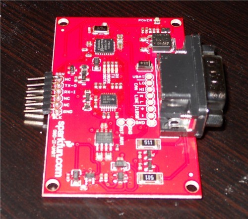
To ensure reliable electrical connections between the OBD2 to serial interface board and external components like an FTDI Basic or Arduino, soldering headers is essential. For straightforward serial communication with an FTDI Basic, male headers soldered into the 6-pin header row on the board’s edge are the most convenient option. After soldering, your board should resemble the image below:
Connecting to Your Vehicle’s OBD Port
The next step is to physically connect your OBD2 to serial interface to your vehicle’s OBD port. The location of this port can vary depending on your car’s make and model. Typically, it’s located under the dashboard on the driver’s side. If you’re unsure of its exact location, consult your vehicle’s owner’s manual for guidance.
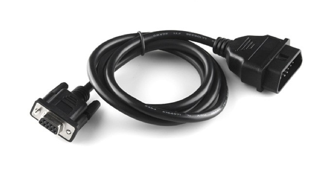
Once you’ve located the OBD port, use an OBD-to-DB9 cable to establish the connection. This cable acts as the intermediary, adapting the OBD port’s connector to the DB9 connector on the OBD2 to serial interface board.
The OBD-II connector on these cables often fits very snugly into the vehicle’s OBD port, requiring a firm push to ensure a secure connection. It’s often easier to first connect the cable to the vehicle before attaching the DB9 end to the OBD2 to serial interface board.
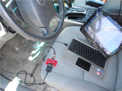
Establishing Serial Communication over FTDI
With headers soldered and the OBD-DB9 cable connecting your OBD2 to serial interface to your car, you’re ready to establish serial communication. An FTDI Basic breakout board serves as the bridge between the serial interface and your computer. The pinout of the FTDI board aligns perfectly with the 6-pin header on the OBD-II UART board, utilizing the TX, RX, and GND connections for serial data transfer. Connect the FTDI board to your computer using a mini-USB cable.
Next, open a serial terminal program on your computer (such as PuTTY, Tera Term, or the Arduino Serial Monitor). Configure the serial connection settings to match the default settings of the OBD2 to serial interface: 9600 bps baud rate, 8 data bits, 1 stop bit, and no parity. These settings ensure proper data exchange between your computer and the OBD-II board.
Once your serial terminal is configured, you can begin communicating with the OBD2 to serial interface using AT commands. These commands are the standard way to interact with ELM327-compatible OBD-II interfaces. AT commands always begin with “AT”, followed by specific command codes. The OBD-II board is case-insensitive, so you can use either uppercase or lowercase letters for commands. A comprehensive list of available AT commands can be found in the ELM327 AT Commands datasheet.
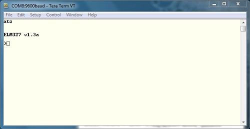
To initiate communication, type “ATZ” in your terminal window and press “Enter”. This command instructs the OBD2 to serial interface to reset. You should observe LEDs flashing on the board, followed by the start-up prompt appearing in your terminal window.
If you encounter garbled characters in the terminal, double-check your serial port settings to ensure they precisely match the required 9600-8-N-1 configuration. Incorrect settings will lead to communication errors.
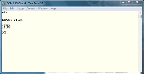
Once you’ve established clean communication, try retrieving the OBD2 to serial interface system voltage. Type “ATRV” into the terminal and press “Enter”. The board should respond by displaying the system voltage.
This voltage reading should closely correspond to your vehicle’s battery voltage, providing a basic confirmation that the OBD2 to serial interface is powered and functioning correctly.
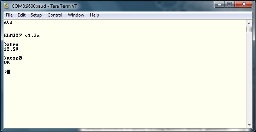
To access vehicle-specific OBD parameters, the OBD2 to serial interface needs to be configured to the correct OBD protocol. There are several different OBD protocols in use, which can initially seem complex. However, this OBD2 to serial interface board has an auto-protocol detection feature to simplify this process. To use this feature, ensure your vehicle’s ignition is in the ‘On’ position (the engine doesn’t need to be running). Then, send the command “ATSP0” (note the trailing zero). The board will automatically detect the correct protocol and respond with “OK” upon successful detection.
With the correct protocol automatically configured, your OBD2 to serial interface is now ready to receive OBD commands and retrieve valuable data from your vehicle.
Understanding OBD Commands for Serial Interface Communication
OBD Command Structure for Serial Interfaces
OBD commands, used to request data through your OBD2 to serial interface, are constructed using hexadecimal codes represented as ASCII characters. Most commands consist of two or more pairs of hexadecimal numbers, although some simpler commands may only require a single hex pair.
The first hexadecimal pair in an OBD command specifies the OBD mode you wish to access. Subsequent hex pairs represent the Parameter ID (PID) that you want to read within that mode. There are 10 defined OBD modes, but it’s important to note that not all vehicles support all 10 modes. You should consult your vehicle’s specific documentation to determine which OBD modes and PIDs are supported.
| Mode Number | Mode Description |
|---|---|
| 01 | Current Data |
| 02 | Freeze Frame Data |
| 03 | Diagnostic Trouble Codes |
| 04 | Clear Trouble Code |
| 05 | Test Results/Oxygen Sensors |
| 06 | Test Results/Non-Continuous Testing |
| 07 | Show Pending Trouble Codes |
| 08 | Special Control Mode |
| 09 | Request Vehicle Information |
| 0A | Request Permanent Trouble Codes |
For a more detailed understanding of OBD PIDs and their functionalities, Wikipedia offers a comprehensive resource on OBD-II PIDs. Keep in mind that some vehicle manufacturers also implement proprietary parameters beyond the standard OBD-II PIDs. Therefore, publicly available PID lists may not be exhaustive for every vehicle. Again, the ELM327 AT Commands datasheet is a valuable reference for exploring supported commands and PIDs for your OBD2 to serial interface.
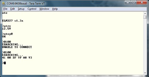
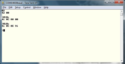
One of the most universally supported PIDs is PID 00. This PID, when queried in Mode 01, provides a list of other PIDs that your vehicle supports. In your serial terminal, type “0100” and press “Enter”. This command translates to “In mode 01, what PIDs are supported by this vehicle?”.
OBD responses generally follow a consistent structure. The first byte in the response (in this example, 0x41) indicates the mode that was requested in your command. It’s calculated as 0x40 + the requested mode (0x01 in this case). The second byte (0x00 here) echoes the parameter that was requested. Subsequent bytes contain the actual data in response to your query. In this example, the bytes 0xBF, 0x9F, 0xA8, and 0x93 represent the PIDs that are supported by the vehicle, encoded in a bitmask format.
Another commonly used parameter is ‘Read Engine RPM’. To retrieve this data, issue the command “010C” and press enter. Remember that the OBD2 to serial interface will respond with values in hexadecimal format.
The response structure remains the same. 0x41 indicates Mode 01, followed by 0x0C for the RPM parameter. The returned value, 0x0E 0x96, is in hexadecimal. Converting 0x0E96 to decimal yields 3734. However, engine RPM is often reported in quarters of RPM by OBD-II. Therefore, dividing 3734 by 4 gives an idling RPM of approximately 933.
Explore the datasheet for the ELM327 for a more extensive list of PIDs to experiment with using your OBD2 to serial interface. Now, let’s move on to integrating the OBD-II board with an Arduino microcontroller.
Connecting Your OBD2 to Serial Interface to an Arduino
Integrating OBD2 Serial Data with Arduino
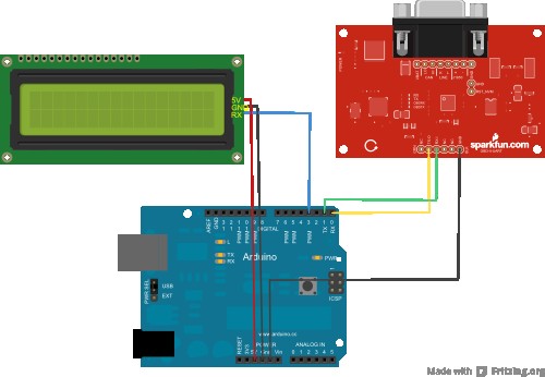
Beyond direct computer connection, your OBD2 to serial interface can be connected to an Arduino board to create embedded vehicle data displays or logging systems. This section will guide you through connecting the OBD-II UART board to an Arduino Uno (or any 5V Arduino board), along with a serial LCD to visualize the data. You’ll also need jumper wires for making the connections.
Only six connections are required between the three devices to set up this system. Refer to the diagram and connection table below for accurate wiring.
| Arduino Pin | Serial LCD Pin | OBD-II-UART Pin |
|---|---|---|
| GND | GND | GND |
| 5V | 5V | None |
| D3 | Rx | None |
| D0(Rx) | None | Tx-O |
| D1(Tx) | None | Rx-I |
Download the Arduino sketch code here. For the most recent version, check the GitHub repository. Important: When uploading the code to your Arduino, disconnect the OBD-II board’s RX line from the Arduino’s TX pin (D1). This prevents potential conflicts and issues during code upload, including the risk of inadvertently affecting the OBD2 to serial interface board.
Another key point for this setup is that the Arduino is not powered by the OBD2 to serial interface board. You’ll need to power the Arduino separately, either via USB from your laptop or using an external power source like a 9V battery with a 9V barrel jack adapter.
Understanding the Arduino Sketch for OBD2 Serial Data Display
This example Arduino sketch is designed for simplicity, focusing on reading data from the OBD2 to serial interface and displaying it on the LCD. The Arduino acts as an intermediary, receiving serial data from the OBD-II UART and forwarding it to the serial LCD. The SoftwareSerial library is used to manage serial communication with the LCD, allowing you to use digital pins 2 and 3 for the LCD’s TX/RX lines. Variables are initialized to store speed and RPM data.
#include <softwareserial.h>

// Create a SoftwareSerial instance for the serial LCD
SoftwareSerial lcd(2, 3); // Arduino pin 3 to LCD Rx

char rxData[20]; // Character buffer for serial data
char rxIndex = 0;

int vehicleSpeed = 0; // Variable to store vehicle speed
int vehicleRPM = 0;    // Variable to store vehicle RPM
In the setup() function, serial communication is initialized for both the LCD and the OBD2 to serial interface at 9600 bps. The LCD screen is cleared, and headers “Speed:” and “RPM:” are printed on the first and second rows, respectively. The OBD2 to serial interface is then reset using the “ATZ” command.
void setup() {
  lcd.begin(9600);      // Initialize LCD serial communication
  Serial.begin(9600);   // Initialize serial for OBD2 interface

  lcd.write(254);       // Clear LCD screen
  lcd.write(1);

  lcd.print("Speed: ");   // Print "Speed:" header
  lcd.write(254);
  lcd.write(128 + 64);  // Move cursor to second row
  lcd.print("RPM: ");     // Print "RPM:" header

  delay(1500);          // Delay before reset command

  Serial.println("ATZ"); // Reset OBD2 serial interface
  delay(2000);          // Delay after reset

  Serial.flush();         // Clear serial input buffer
}
The loop() function is the heart of the sketch. It continuously queries the OBD2 to serial interface for vehicle speed and RPM data, updates the LCD display, and introduces small delays. For each parameter (speed and RPM), the code:
- Clears any residual data in the serial input buffer.
- Positions the LCD cursor to the data display area.
- Clears the previous data on the LCD.
- Sends the OBD command (“010D” for speed, “010C” for RPM) to the OBD2 to serial interface.
- Calls the
getResponse()function (defined later) twice to receive and process the two expected responses (command echo and data). - Converts the received hexadecimal data to integer values for speed and RPM. Note that RPM is adjusted by dividing by 4 as it’s provided in quarter RPM units.
- Prints the extracted speed and RPM values to the LCD, along with units (“km/h”).
- Introduces small delays to control the update rate and avoid overwhelming the OBD bus.
void loop() {
  Serial.flush();         // Clear serial input buffer

  lcd.write(254);
  lcd.write(128 + 8);   // Set cursor for speed data
  lcd.print("      ");    // Clear old speed data
  lcd.write(254);
  lcd.write(128 + 8);   // Reset cursor position

  Serial.println("010D"); // OBD command for Vehicle Speed
  getResponse();          // Get command echo
  getResponse();          // Get speed data

  vehicleSpeed = strtol(&rxData[6], 0, 16); // Convert hex speed to integer
  lcd.print(vehicleSpeed);
  lcd.print(" km/h");

  delay(100);

  Serial.flush();         // Clear serial input buffer

  lcd.write(254);
  lcd.write(128 + 69);  // Set cursor for RPM data
  lcd.print("      ");    // Clear old RPM data
  lcd.write(254);
  lcd.write(128 + 69);  // Reset cursor position

  Serial.println("010C"); // OBD command for Engine RPM
  getResponse();          // Get command echo
  getResponse();          // Get RPM data

  vehicleRPM = ((strtol(&rxData[6], 0, 16) * 256) + strtol(&rxData[9], 0, 16)) / 4; // Convert hex RPM to integer, adjust for quarter RPM
  lcd.print(vehicleRPM);

  delay(100);
}
The getResponse() function is crucial for handling serial data reception from the OBD2 to serial interface. It reads incoming characters from the serial port and stores them in the rxData buffer until a carriage return character (‘r’) is detected, signaling the end of a response. Once a carriage return is received, the buffer is null-terminated to create a valid C-string, the rxIndex is reset for the next data reception, and the function returns. This function ensures that complete OBD responses are captured and processed by the Arduino.
void getResponse(void) {
  char inChar = 0;
  while (inChar != 'r') { // Read until carriage return
    if (Serial.available() > 0) {
      if (Serial.peek() == 'r') { // Check for carriage return
        inChar = Serial.read();    // Consume carriage return
        rxData[rxIndex] = '';   // Null-terminate string
        rxIndex = 0;             // Reset buffer index
      } else {
        inChar = Serial.read();    // Read character
        rxData[rxIndex++] = inChar; // Store character in buffer
      }
    }
  }
}
Important Note on Serial.flush(): Modern Arduino implementations of Serial.flush() only clear the outgoing buffer, not the incoming buffer. If you are using a newer Arduino IDE version and experience issues with data reception, you might need to implement alternative methods for clearing the input buffer before sending new commands. A common approach, as suggested in the Arduino forum, is to use Serial.available() to check the number of bytes in the input buffer and then Serial.read() to read and discard those bytes until the buffer is empty.
Resources and Further Exploration of OBD2 to Serial Interfaces
Now that you have a foundational understanding of working with the OBD2 to serial interface, you can expand your projects and explore more advanced functionalities. Experiment with modifying the Arduino sketch to read and display other Parameter IDs (PIDs) supported by your vehicle. Refer to the ELM327 datasheet and online OBD-II PID resources to discover a wide range of vehicle data you can access.
Software Resources
Beyond programming your own interfaces, several free software applications are available online that can visualize OBD-II data in user-friendly formats like graphs and gauges. These tools often require minimal setup, primarily needing a serial port connection to your OBD2 to serial interface. Explore the software resources available in the GitHub Repository: OBDII_UART/Software for a starting point.
With your OBD2 to serial interface successfully set up and running, you’re well-equipped to integrate it into your own innovative projects. Consider applications like:
- Customizable dashboards: Design personalized displays showing the vehicle parameters most relevant to you.
- Data logging systems: Record vehicle data over time for performance analysis, fuel efficiency studies, or diagnostic purposes.
- Smart car integrations: Combine OBD-II data with other sensors and systems to create advanced vehicle automation or monitoring solutions.
For further learning and inspiration, explore these related tutorials:
### CAN-BUS Shield Hookup Guide
Learn the basics of working with the CAN-Bus protocol and CAN-Bus shields for Arduino.
### Getting Started with OBD-II
A comprehensive overview of OBD-II protocols and their applications in automotive diagnostics.
### AST-CAN485 Hookup Guide
Explore the AST CAN485, a compact Arduino with integrated CAN and RS485 ports for industrial communication.
By leveraging the power of the OBD2 to serial interface, you can unlock a wealth of information from your vehicle and create exciting projects that bridge the gap between your car and the world of electronics.