Need a simple intro to UDS (Unified Diagnostic Services)?
In this practical tutorial, we introduce the Uds Diagnostics protocol basics with a focus on UDS on CAN bus (UDSonCAN) and Diagnostics over CAN (DoCAN). We also introduce the ISO-TP protocol and explain the difference between UDS, OBD2, WWH-OBD, and OBDonUDS in the context of automotive diagnostics.
Finally, we’ll explain how to request, record & decode UDS diagnostics messages – with practical examples for logging EV State of Charge and the Vehicle Identification Number (VIN) for automotive repair and diagnostics.
Bonus: We will also show how UDS diagnostics data can be visualized in dashboards for enhanced automotive diagnostics:
What is the UDS Protocol in Automotive Diagnostics?
Unified Diagnostic Services (UDS) is a crucial communication protocol within automotive Electronic Control Units (ECUs). It’s designed to facilitate comprehensive automotive diagnostics, firmware updates, and routine testing, making it essential for modern vehicle repair and maintenance.
The UDS protocol (ISO 14229) is standardized across various automotive manufacturers and communication standards, including CAN, KWP 2000, Ethernet, and LIN. Today, UDS diagnostics is widely implemented in ECUs across all tier 1 Original Equipment Manufacturers (OEMs), highlighting its importance in the automotive industry.
In practice, UDS communication operates through a client-server model. A tester tool acts as the client, while a vehicle ECU serves as the server. For instance, by connecting a CAN bus interface to a car’s OBD2 connector, you can initiate UDS diagnostics requests. If the ECU supports UDS services, it will respond accordingly, enabling in-depth automotive diagnostics and repair procedures.
Illustration of a UDS protocol service request and response message flow, fundamental to automotive diagnostics.
This communication enables a wide range of use cases in automotive diagnostics:
- Diagnostic Trouble Codes (DTC) Management: Read and clear DTCs to effectively troubleshoot vehicle issues, a cornerstone of automotive repair.
- Parameter Data Extraction: Retrieve critical parameter data values such as temperatures, state of charge (SoC), and VIN, essential for vehicle diagnostics and performance analysis.
- Diagnostic Session Initiation: Start diagnostic sessions to test safety-critical features, crucial for ensuring vehicle safety and reliability.
- ECU Behavior Modification: Modify ECU settings through resets, firmware flashing, and configuration adjustments, key for advanced automotive repair and customization.
UDS diagnostics is often referred to as ‘vehicle manufacturer enhanced diagnostics‘ or ‘enhanced diagnostics‘, emphasizing its advanced capabilities beyond basic diagnostics.
UDS vs CAN Bus: Standards & OSI Model in Automotive Diagnostics
To fully grasp UDS diagnostics, it’s important to understand its relationship with CAN bus and the OSI model, which are fundamental concepts in automotive communication.
As detailed in our CAN bus tutorial, the Controller Area Network (CAN) provides the foundational communication layer in vehicles. CAN is defined by the data-link and physical layers within the OSI model (ISO 11898). In contrast, UDS diagnostics (ISO 14229) is a ‘higher layer protocol‘, utilizing the session layer (5th) and application layer (7th) of the OSI model, as illustrated below:
The 7-layer OSI model highlighting the position of Unified Diagnostic Services (UDS) and its reliance on CAN bus for lower layers.
Overview of UDS Standards & Concepts for Automotive Diagnostics
UDS diagnostics encompasses numerous standards and concepts, which can initially seem complex. To simplify, we provide a high-level overview of the most relevant aspects, particularly focusing on CAN as the underlying communication basis in automotive systems.
Here’s a breakdown of each layer within the OSI model concerning UDS diagnostics:
- Application Layer: Defined by ISO 14229-1 (across various serial data link layers). Further, specific ISO standards detail the UDS application layer for different lower-layer protocols, such as ISO 14229-3 for CAN bus (UDSonCAN).
- Presentation Layer: Vehicle manufacturer specific, allowing for customization in automotive diagnostics implementations.
- Session Layer: Described in ISO 14229-2, managing communication sessions in UDS diagnostics.
- Transport & Network Layer: For CAN, ISO 15765-2 (ISO-TP) is used, handling data transport in automotive networks.
- Data Link Layer: In CAN, this is defined by ISO 11898-1, ensuring reliable data links.
- Physical Layer: For CAN, ISO 11898-2 specifies the physical interface, crucial for robust automotive communication.
As shown, UDS diagnostics can be implemented over various communication protocols beyond CAN, including FlexRay, Ethernet, LIN bus, and K-line. However, this guide primarily focuses on CAN, the most prevalent lower-layer protocol in automotive applications.
The ISO 14229-1 standard sets the application layer requirements for UDS diagnostics, irrespective of the lower-layer protocol used. It specifically outlines:
- Client-server communication flows (requests, responses, etc.) in automotive diagnostics.
- UDS services, as previously overviewed, essential for different diagnostic functions.
- Positive responses and negative response codes (NRCs) in UDS diagnostics communication.
- Various definitions (e.g., DTCs, parameter data identifiers or DIDs) used in automotive diagnostics.
The purpose of ISO 14229-3 is to standardize the implementation of Unified Diagnostic Services (UDS) on Controller Area Networks (CAN), commonly known as UDSonCAN. This standard details the application layer requirements specific to UDSonCAN in automotive diagnostics.
It’s important to note that this standard does not dictate any in-vehicle CAN bus architecture implementation requirements. Instead, it focuses on additional requirements and restrictions for UDS that are specific to UDSonCAN, ensuring compatibility and efficiency in automotive diagnostics.
Specifically, ISO 14229-3 identifies which UDS services have CAN-specific requirements. These primarily include ResponseOnEvent and ReadDataByPeriodicIdentifier, for which CAN-specific requirements are detailed in 14229-3. All other UDS services are implemented as per ISO 14229-1 and ISO 14229-2, maintaining consistency across UDS diagnostics.
ISO 14229-3 also specifies mappings between ISO 14229-2 and ISO 15765-2 (ISO-TP) and outlines requirements related to 11-bit and 29-bit CAN IDs when used for UDS and legislated OBD as per ISO 15765-4, ensuring interoperability in automotive diagnostics.
This standard defines the session layer within the UDS OSI model. It specifies service request/confirmation/indication primitives, providing a standardized interface for implementing UDS (ISO 14229-1) over various communication protocols, including CAN. This is vital for ensuring consistent UDS diagnostics across different automotive communication systems.
For UDS on CAN, ISO 15765-2 describes how to transmit diagnostic requests and responses. Critically, it details how to structure CAN frames to facilitate the communication of multi-frame payloads, essential for handling larger diagnostic data in automotive networks. This is a vital aspect of understanding UDS on CAN, which we will explore further.
When UDS is implemented over CAN bus, the physical and data link layers are defined by ISO 11898-1 and ISO 11898-2. In this context, UDS can be considered a higher-layer protocol, similar to J1939, OBD2, CANopen, NMEA 2000, etc. However, unlike these protocols, UDS is versatile and can be based on alternative communication protocols such as FlexRay, Ethernet, LIN, and others, offering flexibility in automotive diagnostics implementations.
When discussing UDS diagnostics based on CAN bus, you’ll frequently encounter the terms UDSonCAN (UDS on CAN bus) and DoCAN (Diagnostics on CAN bus). Some UDS tutorials use these terms interchangeably, which can lead to confusion.
In ISO 14229-1, these terms are used as depicted in our OSI model illustration. UDSonCAN specifically refers to ISO 14229-3, whereas DoCAN refers to ISO 15765-2, also known as ISO-TP.
However, the confusion partly arises because ISO 14229-3 also presents an OSI model where DoCAN is used in relation to both ISO 15765-2 and as an overlay across OSI model layers 2 to 7. In ISO 14229-2, DoCAN is referenced as the communication protocol upon which UDS (ISO 14229-1) is implemented. This aligns with the illustration in ISO 14229-3. In this context, DoCAN can be seen as a broader term for implementing UDS on CAN, while UDSonCAN consistently refers specifically to ISO 14229-3.
UDS on CAN bus (UDSonCAN) is sometimes incorrectly referenced as ISO 15765-3. It’s important to note that this standard is now obsolete and has been superseded by ISO 14229-3 in the context of automotive diagnostics.
Get our ‘Ultimate CAN Guide’ for Automotive Diagnostics
Want to become a CAN bus expert in automotive diagnostics?
Get our 12 ‘simple intros’ in one 160+ page PDF:
Download now
UDS Diagnostics – No Standard Connector?
Unlike other higher-layer CAN protocols such as OBD2, J1939, and ISOBUS, UDS diagnostics does not specify a standard connector for connecting external diagnostic equipment. This contrasts with other protocols in automotive diagnostics.
However, in practice, the OBD2 connector (SAE J1962) is commonly used in most vehicles for UDS diagnostics. For example, electric vehicles from Nissan, Hyundai, and VW may have limited or no OBD2 communication but often respond to UDS requests via the OBD2 connector, making it a practical interface for automotive diagnostics.
UDS Message Structure [ISO 14229-1/3] for Automotive Diagnostics
UDS diagnostics is fundamentally a request-based protocol. The illustration below outlines an example of a UDS request frame using CAN bus as the communication medium:
A typical UDS message frame structure on CAN bus, illustrating the components essential for automotive diagnostics requests.
A diagnostic UDS request on CAN includes several fields, which are detailed below:
#1 Protocol Control Information (PCI) in UDS Diagnostics
The PCI field is not directly related to the UDS request itself but is essential for UDS diagnostics requests over CAN bus. It’s linked to ISO-TP (ISO 15765-2), as will be explained. The example shown is a ‘Single Frame’ ISO-TP CAN message, a basic type in automotive diagnostics communication.
#2 UDS Service ID (SID) for Automotive Diagnostics
The use cases for UDS diagnostics are categorized into different UDS services. When you want to utilize a specific UDS service, the UDS request message must include the UDS Service Identifier (SID) in the data payload. SIDs are differentiated into request SIDs (e.g., 0x22) and response SIDs (e.g., 0x62). Similar to OBD2, response SIDs are typically obtained by adding 0x40 to the request SIDs, a common practice in automotive diagnostics.
Refer to the overview of all standardized UDS services and SIDs for a comprehensive understanding. In this article, we primarily focus on UDS service 0x22, which is used to read data (e.g., speed, SoC, temperature, VIN) from an ECU, a crucial service in automotive diagnostics.
Overview table of UDS services, highlighting services 0x22 and 0x19, which are frequently used in automotive diagnostics.
The standardized UDS services shown are a subset of a broader range of diagnostic services – see the overview below. Note that SIDs 0x00 to 0x0F are reserved for legislated OBD services, indicating the integration of UDS with standard OBD functions in automotive diagnostics.
UDS diagnostics provides extensive control over vehicle ECUs. For security reasons, critical UDS services are often protected by an authentication process. An ECU will send a ‘seed’ to a tester, which must then generate a ‘key’ to access security-sensitive services. To maintain this access, the tester must periodically send a ‘tester present’ message, a security measure in advanced automotive diagnostics.
This authentication process allows vehicle manufacturers to restrict UDS access for aftermarket users, ensuring that only authorized tools can utilize security-critical UDS services. This is vital for protecting vehicle systems and maintaining OEM control over advanced automotive diagnostics.
Diagnostic session control manages the switching between authentication levels, a standard UDS service. Vehicle manufacturers decide which sessions are supported, but they must always support the ‘default session’ (without authentication). However, they also determine the services available within the default session. If a tester tool switches to a non-default session, it must send a ‘tester present’ message periodically to avoid reverting to the default session, managing access levels in automotive diagnostics.
#3 UDS Sub Function Byte in Automotive Diagnostics
The sub function byte is used in some UDS request frames, as outlined below. However, it’s important to note that some UDS services, like 0x22, do not utilize the sub function byte, showing variability in UDS diagnostics message structures.
Generally, when a request is sent to an ECU, the ECU may respond positively or negatively. If the response is positive, the tester might want to suppress the response if it’s not needed. This is achieved by setting the 1st bit to 1 in the sub function byte. Negative responses, however, cannot be suppressed, ensuring critical error reporting in automotive diagnostics.
The remaining 7 bits can define up to 128 sub function values, allowing for extensive customization within UDS diagnostics services.
Example: Service 0x19 Sub Functions for DTC Reading in Automotive Diagnostics
When reading DTC information via SID 0x19 (Read Diagnostic Information), the sub function byte is used to control the report type, as shown in the table. This is a common application in automotive diagnostics for fault code management.
For instance, sub function byte 0x02 allows reading DTCs via a status mask. In this case, the sub function byte is followed by a 1-byte parameter called DTC Status Mask, providing further request details. Another common example is sub function byte 0x42, used for reading DTCs via WWH-OBD. This requires 3 additional bytes to configure the request, as seen in our trace example later, demonstrating specific implementations in automotive diagnostics.
UDS sub-function byte table for diagnostic trouble codes (DTC) under service 0x19, detailing options for automotive diagnostics error reporting.
#4 UDS ‘Request Data Parameters’ – incl. Data Identifier (DID) in Automotive Diagnostics
In most UDS request services, various request data parameters are used to further configure a request beyond the SID and optional sub function byte. These parameters are essential for specifying the exact data or action required in automotive diagnostics.
Example: Service 0x22 DIDs for Data Reading in Automotive Diagnostics
A key example is service 0x22 (Read Data by Identifier). This service uses a Data Identifier (DID), a 2-byte value ranging from 0 to 65535 (0xFFFF). The DID acts as a parameter identifier for both requests and responses, similar to the parameter identifier (PID) in OBD2. Service 0x22 does not use a sub function byte, simplifying its structure in automotive diagnostics.
For example, a request to read data via a single DID in UDS over CAN would include the PCI field, the UDS service 0x22, and the 2-byte DID. Data for multiple DIDs can be requested by appending them after the initial DID in the request, enhancing data retrieval efficiency in automotive diagnostics.
We will explore this further in the section on recording and decoding UDS communication.
Data Identifiers can be proprietary, known only to OEMs, but some DIDs are standardized. This standardization is seen in WWH-OBD DIDs and the Vehicle Identification Number (VIN) DID 0xF190. A separate table lists standardized DIDs across UDS, facilitating common data access in automotive diagnostics.
Positive vs. Negative UDS Responses [ISO 14229-1] in Automotive Diagnostics
When an ECU responds positively to a UDS request, the response frame is structured similarly to the request frame. For example, a ‘positive’ response to a service 0x22 request will include the response SID 0x62 (0x22 + 0x40), the 2-byte DID, and the actual data payload for the requested DID. The structure of a positive UDS response message generally depends on the specific service used in automotive diagnostics.
However, in some cases, an ECU may provide a negative response to a UDS request, such as if a service is not supported or if there’s an error. A negative response is structured as shown in the CAN frame example below:
Example of a negative response frame in Unified Diagnostic Services (UDS), indicating error conditions in automotive diagnostics.
The negative response frame is composed of:
- The 1st byte: PCI field (ISO-TP Single Frame).
- The 2nd byte: Negative Response Code SID, 0x7F, indicating a negative response in UDS diagnostics.
- The 3rd byte: SID of the rejected request, specifying which service was not successful.
- The 4th byte: Negative Response Code (NRC), detailing the reason for the rejection in automotive diagnostics.
In a negative UDS response, the NRC provides information about why the request was rejected, as per the table below. In this example, the frame suggests that a request was made using SID 0x22 (Read Data by Identifier), but it failed due to an invalid message format or length, providing crucial feedback in automotive diagnostics troubleshooting.
CAN ISO-TP – Transport Protocol [ISO 15765-2] for Large Data in Automotive Diagnostics
Implementing diagnostics on CAN bus presents a challenge due to the CAN frame payload size limitation. Classical CAN frames are limited to 8 bytes, and CAN FD frames to 64 bytes. However, vehicle diagnostics often involves transmitting much larger payloads.
ISO 15765-2 was established to address this payload size challenge for CAN-based vehicle diagnostics. It’s crucial for handling extensive data in automotive communication.
The standard specifies a transport protocol and network layer services for CAN-based vehicle networks. Common applications include UDS (ISO 14229-1), OBD (SAE J1979, ISO 15031-5), and world-wide harmonized OBD (WWH-OBD) (ISO 27145). ISO-TP is vital for enabling these protocols to function effectively in automotive diagnostics.
The ISO-TP standard details how to communicate CAN data payloads up to 4095 bytes through segmentation, flow control, and reassembly. ISO-TP defines specific CAN frame types to enable this communication, as shown below:
CAN ISO-TP frame types: Single Frame (SF), First Frame (FF), Consecutive Frame (CF), and Flow Control (FC), essential for managing large data transfers in automotive diagnostics.
The flow control frame is used to ‘configure’ the subsequent communication, managing data flow in automotive networks. It can be structured as follows:
ISO-TP Flow Control Frame types, detailing options for managing data transmission rates and flow in automotive diagnostics.
Key points about ISO-TP frames:
-
In the simplest case, the FC payload can be set to 30 00 00 00 00 00 00 00 (all remaining frames to be sent without delay), facilitating straightforward data transmission in automotive diagnostics.
-
Alternatively, more granular control over communication can be achieved by alternating between Wait and Continue commands and specifying a separation time (in milliseconds) between frames, allowing for optimized data flow in automotive networks.
-
The ISO-TP frame type is identified by the first nibble of the first byte (0x0, 0x1, 0x2, 0x3), simplifying frame interpretation in automotive diagnostics.
-
The total frame size can be up to 4095 bytes (0xFFF), as indicated by the FF frame, accommodating large diagnostic data sets in automotive systems.
-
The CF index ranges from 1 to 15 (0xF) and resets if more data needs to be sent, managing sequential data packets in automotive communication.
-
Padding (e.g., 0x00, 0xAA, etc.) is used to ensure frame payloads are 8 bytes long, standardizing frame size in CAN communication for automotive diagnostics.
Below, we outline how the ISO-TP protocol works for single-frame and multi-frame communication, illustrating different scenarios in automotive diagnostics data exchange.
ISO-TP: Single-Frame Communication in Automotive Diagnostics
In vehicle diagnostics, communication starts with a tester tool sending a request. This initial request frame is a Single Frame (SF), initiating the diagnostic process.
In the simplest scenario, a tester tool sends a Single Frame to request data from an ECU. If the response fits within a 7-byte payload, the ECU provides a Single Frame response, completing a basic diagnostic data exchange.
ISO-TP Single Frame request and response communication flow in UDS, illustrating basic data exchange in automotive diagnostics.
ISO-TP transport protocol in UDS on CAN bus, detailing multi-frame communication for larger data sets in automotive diagnostics.
ISO-TP: Multi-Frame Communication in Automotive Diagnostics
When the payload exceeds 7 bytes, it must be divided across multiple CAN frames. This is where multi-frame communication becomes essential in automotive diagnostics.
As before, a tester sends a Single Frame (SF) request to an ECU (sender). However, in this case, the expected response is larger than 7 bytes, necessitating a multi-frame approach for automotive diagnostics data transfer.
Because of this, the ECU sends a First Frame (FF), which contains information about the total packet length (8 to 4095 bytes) and the initial data chunk. The First Frame sets up the multi-frame communication process in automotive diagnostics.
Upon receiving the FF, the tester sends a Flow Control (FC) frame. This frame instructs the ECU on how to proceed with the rest of the data transmission. Flow Control is crucial for managing multi-frame data flow in automotive diagnostics.
Following the FC frame, the ECU sends Consecutive Frames (CF). These frames contain the remaining data payload, segmented to fit within CAN frame limits. Consecutive Frames ensure the complete transmission of large diagnostic data sets in automotive systems.
ISO-TP is integral to most CAN-based diagnostics protocols, enabling efficient handling of both small and large data packets. Before demonstrating practical examples of these communication flows, it’s beneficial to overview common vehicle diagnostic protocols in automotive systems.
UDS vs. OBD2 vs. WWH-OBD vs. OBDonUDS in Automotive Diagnostics
A common question is how UDS relates to On-Board Diagnostics (OBD2), World-Wide Harmonized OBD (WWH-OBD), and OBDonUDS. To understand this, it’s important to first note that OBD (On-Board Diagnostics) is implemented differently across countries and vehicle manufacturers, leading to variations in automotive diagnostics standards.
This is illustrated in the OSI model below, which includes CAN-based vehicle diagnostic protocols currently in use:
OSI model of vehicle diagnostic protocols, comparing WWH-OBD, ISO-OBD, SAE HD OBD, and UDS in the context of automotive diagnostics.
Let’s examine each diagnostic protocol in relation to automotive diagnostics:
- ISO OBD (or EOBD) refers to the OBD protocol specification mandated for EU cars, while SAE OBD is for US cars. They are technically equivalent and often referred to simply as OBD or OBD2, forming the basis of standard automotive diagnostics.
- HD OBD (SAE J1939) typically refers to heavy-duty OBD, commonly implemented through the J1939 protocol in vehicles in both US and EU. J1939-73 specifies diagnostic messages for heavy-duty automotive diagnostics.
- UDS (ISO 14229) has been adopted by vehicle manufacturers to meet the need for richer diagnostics data and functionality beyond the limits of emissions-focused OBD protocols. It’s implemented in most ECUs today across markets and vehicle types. However, UDS alone lacks the standardization to replace OBD, serving as enhanced automotive diagnostics.
- WWH-OBD (and/or possibly OBDonUDS) provide an updated version of OBD2 for emissions-related diagnostics, based on UDS. These represent the evolution of standardized automotive diagnostics.
To understand UDS diagnostics better, it is useful to understand WWH-OBD and OBDonUDS in detail:
What is WWH-OBD (ISO 27145) in Automotive Diagnostics?
WWH-OBD is a global standard for vehicle diagnostics, developed by the UN under the Global Technical Regulations (GTR) mandate. It aims to provide a single, future-proof alternative to existing OBD protocols (ISO OBD, SAE OBD, HD OBD), representing a unified approach to automotive diagnostics. WWH-OBD is based on UDS to leverage the enhanced diagnostics functionality already deployed by most automotive OEMs today, combining standardization with advanced features.
Moving from OBD2 to WWH-OBD offers several benefits, primarily from using the UDS protocol as its foundation for enhanced automotive diagnostics.
Firstly, data richness can be significantly increased. OBD2 parameter identifiers (PIDs) are limited to 1 byte, restricting unique data types to 255, while UDS data identifiers (DIDs) are 2 bytes, allowing for 65535 parameters. This expansion greatly enhances the depth of automotive diagnostics data available.
For diagnostic trouble codes (DTCs), OBD2 allows for 2-byte DTCs. WWH-OBD introduces ‘extended DTCs’ of 3 bytes. This enables grouping DTCs by 2-byte types and using the 3rd byte as a failure mode indicator to specify the DTC subtype, providing more detailed fault information in automotive diagnostics.
Furthermore, WWH-OBD enables DTC classification based on the severity of an issue concerning exhaust emissions quality. This is crucial for prioritizing and addressing emissions-related faults in automotive repair.
WWH-OBD also considers future requirements by allowing Internet Protocol (IP) to be used as an alternative to CAN. This means UDSonIP will be possible in future WWH-OBD implementations. A potential benefit is the ability to perform remote diagnostics using the same protocol, opening new possibilities in automotive service and maintenance.
WWH-OBD is intended to be a global standard across all markets and vehicle types (cars, trucks, buses, etc.). The goal is to potentially expand standardized functionality beyond just emissions control, making it a comprehensive solution for future automotive diagnostics.
In practice, WWH-OBD has been mandatory in the EU since 2014 for newly developed heavy-duty vehicles (as per Euro-VI standards). Note that HD OBD (as per J1939) remains permissible in these vehicles, indicating a transitional phase in automotive diagnostics standards.
However, the broader adoption of WWH-OBD has been limited. One challenge is that WWH-OBD is not currently accepted by EPA/CARB in the USA. Recently, OBDonUDS (SAE J1979-2) is being adopted in the US as an alternative direction for advanced automotive diagnostics.
Diagram explaining World-Wide Harmonized OBD (WWH-OBD) and its global standardization efforts in automotive diagnostics.
Timeline overview of OBDonUDS history and future roadmap, illustrating the evolution of OBD standards in automotive diagnostics.
What is OBDonUDS (SAE J1979-2) in Automotive Diagnostics?
Similar to how OBD2 was divided into ‘SAE OBD’ (SAE J1979) for the US and ‘ISO OBD’ (ISO 15031) for the EU, the ‘next generation’ of OBD2 may again be regionally split in automotive diagnostics.
Specifically, WWH-OBD (ISO 27145) has been adopted in the EU for heavy-duty vehicles but not yet in the US. Instead, the US has recently decided to adopt OBD on UDS in the form of the SAE J1979-2 standard, an update to SAE J1979. This new standard, SAE J1979-2, is also known as OBDonUDS, marking a regional divergence in automotive diagnostics. The aim is to start a transition phase in 2023, allowing ECUs to support either OBD2 or OBDonUDS. From 2027, OBDonUDS will become mandatory for all vehicles produced in the US, setting a clear direction for future automotive diagnostics in the region.
To summarize, WWH-OBD and OBDonUDS are potential solutions for creating a ‘next generation’ protocol for emissions-related on-board diagnostics. It remains to be seen if they will coexist (like ISO/SAE OBD) or if one will become the de facto standard across the US, EU, and beyond in automotive diagnostics.
In either scenario, UDS will be the foundation for emissions-related diagnostics. This simplifies ECU programming, as emissions diagnostics can be increasingly integrated into the same UDS-based structure as manufacturer-specific enhanced diagnostics, streamlining automotive diagnostics development and implementation.
The CAN Calibration Protocol (CCP) and the Universal Measurement and Calibration Protocol (XCP) on CAN are higher-layer CAN protocols typically used by automotive OEM engineers in early prototype development. They enable ECU measurement and calibration. For a comparison with UDS, see our intro to CCP/XCP on CAN, providing context within automotive diagnostics toolsets.
How to Request/Record UDS Data for Automotive Diagnostics
We have now covered the basics of UDS and ISO-TP, providing a foundation for understanding advanced automotive diagnostics.
With this understanding, we can offer practical guidance on using UDS data in real-world scenarios. We will focus particularly on how UDS can be used to log various data parameters, such as the state of charge (SoC) in electric vehicles, a critical aspect of modern automotive diagnostics.
Before diving into examples, let’s address frequently asked questions about UDS data logging in automotive diagnostics:
A standalone UDS data logger, illustrating hardware used for recording and analyzing automotive diagnostics data.
Yes, as we will demonstrate, the CANedge can be configured to request UDS data. This device can be set up to transmit up to 64 custom CAN frames as periodic or single-shot frames. Users have control over CAN ID, CAN data payload, period time, and delay, offering flexibility in automotive diagnostics data acquisition.
For single-frame UDS communication, configure the CANedge with the request frame. This will trigger a single response frame from the ECU, simplifying basic automotive diagnostics data retrieval.
For multi-frame communication, again, configure the CANedge with a request frame and then add the Flow Control frame as a separate frame to be transmitted X milliseconds after the request frame. By adjusting the timing, you can ensure the Flow Control is sent after the ECU has sent the First Frame response, enabling complex data logging in automotive diagnostics.
Diagram showing how an OBD2 data logger records vehicle data, similar principles apply to UDS data logging in automotive diagnostics.
Note that the CANedge records UDS responses as raw CAN frames. This data can be processed and decoded using your preferred software, such as Vector tools, Python, or MF4 decoders. These tools are essential for analyzing automotive diagnostics data.
A common use case for recording UDS data via ‘standalone’ data loggers is to acquire diagnostic trouble code values, useful for diagnosing vehicle issues. DTC logging is a fundamental aspect of automotive diagnostics.
In addition to trouble codes, UDS allows you to request the ‘current value’ of various sensors related to each ECU. This enables OEMs, fleet managers, researchers, etc., to collect data of interest like speed, RPM, state of charge, temperatures, etc., from vehicles, provided they know how to request and decode the data. This sensor data is invaluable for vehicle diagnostics and performance monitoring.
Beyond these applications, UDS can also be used for lower-level ECU control, such as resets and firmware flashing. However, these more advanced functions are typically performed using a CAN bus interface rather than a standalone device, reflecting different levels of access and control in automotive diagnostics.
Importantly, UDS is a manufacturer-specific diagnostic protocol, meaning its implementation and parameters vary across vehicle brands and models. This proprietary nature is a key consideration in automotive diagnostics.
While UDS provides a standardized structure for diagnostic communication, the actual ‘content’ of this communication remains proprietary and is generally known only to the vehicle/ECU manufacturer. This specificity is a challenge for aftermarket automotive diagnostics.
For instance, UDS standardizes how to request parameter data from an ECU via the ‘Read Data By Identifier’ service (0x22). However, it does not provide a standardized list of identifiers or interpretation rules. This lack of universal standardization impacts aftermarket automotive diagnostics.
However, vehicles supporting WWH-OBD or OBDonUDS may support some standard OBD2 PIDs like speed and RPM via standard PID values, often prefixed with 0xF4, indicating a degree of overlap and transition in automotive diagnostics standards.
Generally, only the manufacturer (OEM) knows how to request proprietary parameters via UDS and how to interpret the results. Exceptions occur when companies or individuals successfully reverse engineer this information. Reverse engineering is complex, but sometimes public information and DBC files emerge, providing insights into proprietary automotive diagnostics. Our intro to DBC files lists public DBC/decoding databases, which can be resources for automotive diagnostics data.
Due to the proprietary nature of UDS communication, it is most relevant to automotive engineers working at OEMs. Tools like the CANedge CAN bus data logger enable these users to record raw CAN traffic and request diagnostic trouble codes and specific parameter values via UDS. This is crucial for OEM-level automotive diagnostics and development.
Furthermore, some aftermarket users like fleet managers and even private individuals can benefit from UDS if they can identify reverse-engineered information to request and decode UDS parameters of interest. This opens up possibilities for advanced aftermarket automotive diagnostics.
Logging UDS data is also increasingly relevant as WWH-OBD is rolled out. WWH-OBD has been used in EU heavy-duty vehicles since 2014, making UDS communication essential for on-board diagnostics in these vehicles. This trend highlights the growing importance of UDS in automotive diagnostics.
If your goal is to request UDS-based diagnostic trouble codes (DTCs), UDS communication is necessary. However, for recording current sensor values, the choice is less clear. Alternative approaches may exist for sensor data acquisition in automotive diagnostics.
Typically, data parameters of interest for vehicle telematics (speed, state of charge, etc.) are already communicated between ECUs on the CAN bus as raw CAN frames, without needing a diagnostic tool to request this information. ECUs rely on this communication for their operation, as explained in our intro to CAN bus. This direct CAN data logging can be more straightforward for certain automotive diagnostics applications.
If you have direct CAN bus access, logging raw CAN traffic and processing it might seem easier. Vehicle manufacturers know how to interpret this raw CAN data, simplifying device configuration and post-processing. In the aftermarket, reverse engineering raw CAN frames can also be simpler, focusing on Single Frames and avoiding the request/response complexity of UDS. This direct approach can be effective for specific automotive diagnostics needs.
Illustration of an automotive car with a CAN bus system, emphasizing the underlying communication network for automotive diagnostics.
Diagram showing OBD2 connector access blocked by a central gateway, a common scenario driving the need for UDS diagnostics via OBD2.
However, a key reason UDS is frequently used for sensor value extraction, despite the above, is due to ‘gateways’. Modern cars increasingly block raw CAN bus data access via the OBD2 connector, especially in German vehicles and electric vehicles. This trend necessitates alternative diagnostic methods in automotive repair.
To record existing CAN traffic in such cars, tools like a CANCrocodile adapter, ‘snapping’ onto the CAN wiring harness, are needed. This requires wiring harness exposure, often impractical. In contrast, OBD2 connector gateways typically still allow UDS communication, including sensor value communication, making UDS via OBD2 a practical alternative for automotive diagnostics.
A secondary reason is that most reverse engineering efforts are done by ‘OBD2 dongle manufacturers’. These manufacturers develop tools to extract data across many cars via the OBD2 connector. Increasingly, the only way for these dongles to get useful information through OBD2 is via UDS communication. This drives a proportionally higher availability of information/databases related to UDS parameters versus raw CAN parameters, influencing the landscape of aftermarket automotive diagnostics.
Since most ECUs today support UDS communication, the answer is generally “yes, most likely.” UDS diagnostics has become a widely supported standard in modern vehicles.
Vehicle manufacturers typically have the information to construct UDS requests for needed data and know how to decode it, facilitating OEM-level automotive diagnostics.
For WWH-OBD data recording in EU trucks, standardized DID information can be recorded by both OEMs and aftermarket users, similar to recording public OBD2 PIDs from cars/trucks. This standardization benefits both OEM and aftermarket automotive diagnostics.
However, for aftermarket users wishing to record proprietary UDS information from a car/truck, it can be challenging. Options include contacting the OEM (as a system integrator/partner) or attempting reverse engineering. Reverse engineering is generally impractical for most, limiting aftermarket access to proprietary automotive diagnostics data.
In select cases, public information, e.g., on GitHub, may assist in constructing UDS requests and decoding responses. However, public resources are based on reverse engineering and may be incorrect or outdated. Information from such sources should be used cautiously in automotive diagnostics applications.
If your use case involves recording data from cars produced between 2008 and 2018, you will often be interested in data collected via OBD2 data logging. Most ICE cars after 2008 support many public OBD2 parameter identifiers like speed, RPM, throttle position, fuel level, etc., making OBD2 suitable for many automotive diagnostics needs in this vehicle age range.
However, OBD2 data availability is expected to decline over time for several reasons. The shift in automotive diagnostics is moving away from traditional OBD2.
Firstly, as previously explained, WWH-OBD (based on UDS) or OBDonUDS are expected to gradually replace OBD2 as the standard for vehicle diagnostics. This transition signals a move towards UDS-centric automotive diagnostics.
Secondly, with the rise of electric vehicles, legislated OBD2 is not always supported. Even if EVs support some OBD2 PIDs, critical EV parameters like State of Charge (SoC) and State of Health (SoH) are not available via OBD2. In contrast, UDS remains supported in most EVs and provides access to a broader data range. While UDS lacks the aftermarket convenience of a public parameter list (currently), it is becoming increasingly important. EV sales are projected to surpass ICE car sales between 2030 and 2040, making UDS communication increasingly relevant in automotive diagnostics for the future EV market.
About the CANedge CAN Logger for Automotive Diagnostics
The CANedge allows easy recording of CAN/UDS data onto an 8-32 GB SD card. It’s customizable for sending specific CAN frames, including custom UDS requests and flow control frames. Data can be processed via free software/API tools, offering a comprehensive solution for automotive diagnostics data logging and analysis.
Learn about the CANedge
Example 1: Record Single Frame UDS Data (Speed via WWH-OBD) for Automotive Diagnostics
To demonstrate UDS in practice, we begin with a basic example of automotive diagnostics data retrieval.
As explained, WWH-OBD is based on UDS and is mandated in all EU trucks since 2014. Consequently, speed, RPM, fuel level, etc., can typically be requested similarly to OBD2. However, in WWH-OBD (ISO 27145-2), OBD2 PIDs are replaced by WWH-OBD DIDs (Data Identifiers). This shift is important for understanding modern automotive diagnostics.
Specifically, WWH-OBD DIDs match OBD2 PIDs, except 0xF4 is prefixed. For example, OBD2 PID for Speed is 0x0D, which becomes 0xF40D in WWH-OBD. This mapping facilitates a transition from OBD2 to WWH-OBD in automotive diagnostics.
We can use a CANedge3 to send/receive CAN frames. To request Speed via WWH-OBD, we use UDS SID 0x22 (Read Data by Identifier) and DID 0xF40D. The resulting payload can be decoded as per our OBD2 intro, yielding a vehicle speed of 1 * 0x32 = 50 km/h. This example shows practical data extraction in automotive diagnostics.
WWH-OBD World Wide Harmonized Speed PID example, illustrating data logging for speed in automotive diagnostics.
Note the request is sent with CAN ID 0x18DB33F1. This 29-bit CAN ID is used for functionally addressed OBD2 PID requests in heavy-duty vehicles, comparable to the 11-bit 0x7DF CAN ID for OBD2 requests in cars. The response has CAN ID 0x18DAF100, a physical response ID matching those in regular OBD2 responses from heavy-duty vehicles, maintaining consistency in automotive diagnostics communication.
Let’s break down the message payloads of this communication flow:
First, the CANedge2 sends a Single Frame (SF) request:
- The initial 4 bits of the PCI field indicate the frame type (0x0 for SF).
- The next 4 bits of the PCI field indicate the request length (3 bytes).
- The 2nd byte contains the Service Identifier (SID), 0x22.
- The 3rd and 4th bytes contain the DID for Vehicle Speed in WWH-OBD (0xF40D).
- The remaining bytes are padding, standard practice in CAN communication.
In response, the truck sends a Single Frame (SF) response:
- The 1st byte again reflects the PCI field (now with a length of 4 bytes).
- The 2nd byte is the response SID for Read Data by Identifier (0x62, i.e., 0x22 + 0x40).
- The 3rd and 4th bytes again contain the DID 0xF40D, echoing the request.
- The 5th byte contains the Vehicle Speed value, 0x32.
Here, we use the same decoding rules as for ISO/SAE OBD2. The physical Vehicle Speed value is the decimal form of 0x32, i.e., 50 km/h. See our OBD2 PID conversion tool for more details. The decoding process is consistent across OBD2 and WWH-OBD in automotive diagnostics.
If you are familiar with logging OBD2 PIDs, WWH-OBD requests are very similar, except for using the UDSonCAN payload structure for requests and responses. This similarity eases the transition to WWH-OBD in automotive diagnostics.
Example 2: Record Multi-Frame UDS Data (EV SoC%) for Automotive Diagnostics
In this section, we illustrate multi-frame UDS communication in the context of CAN ISO-TP, demonstrating advanced automotive diagnostics data handling.
Specifically, we use the CANedge and UDS SID 0x22 to request the State of Charge (SoC%) from a Kia EV6 electric vehicle (see our case study). This example highlights EV-specific automotive diagnostics.
First, the CANedge is configured to send two CAN frames:
- A Single Frame (SF) request (period: 5000 ms, delay: 0 ms).
- A Flow Control (FC) frame (period: 5000 ms, delay: 100 ms).
Below is a subset of the resulting communication flow for EV SoC% data in automotive diagnostics:
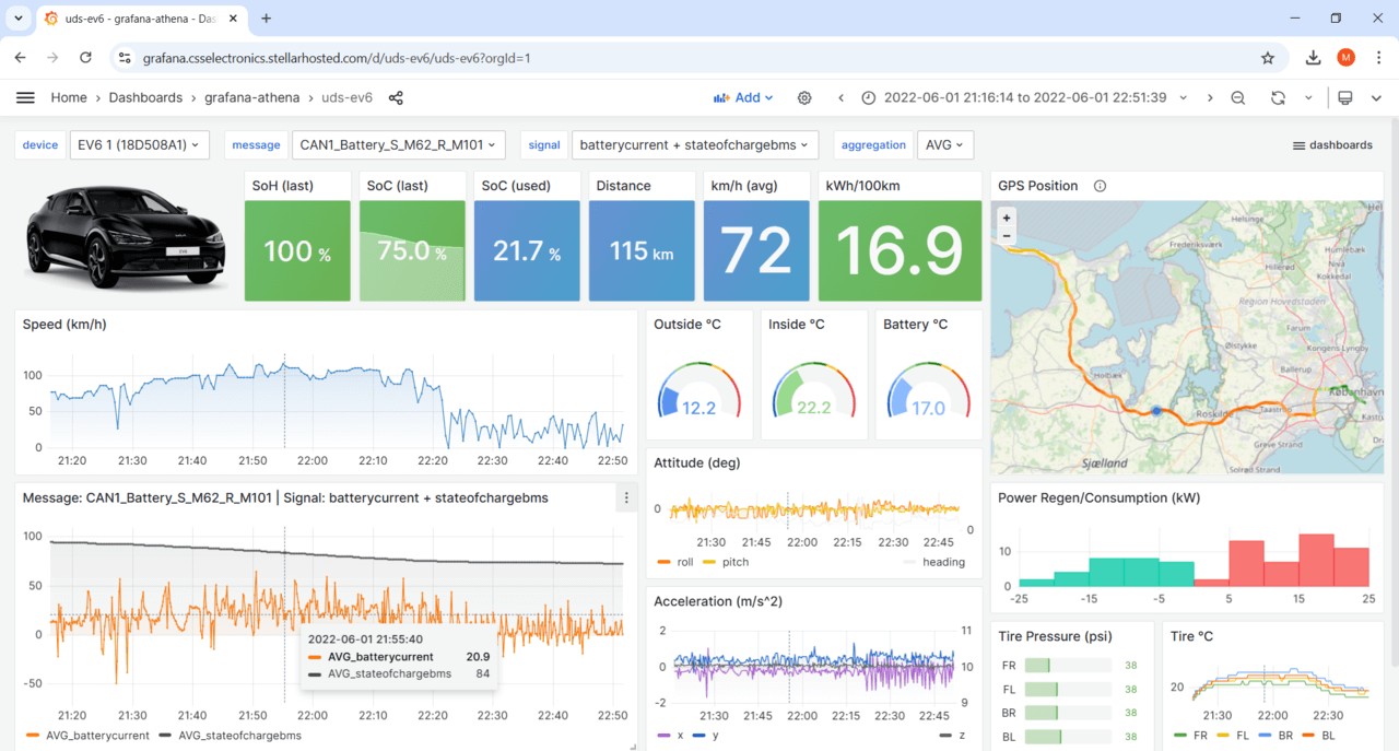
The CANedge can be used to request UDS data from e.g. the Kia EV6 for visualization – learn more in our telematics dashboards intro.
In the following, we explore this communication between the CANedge and ECU in detail, breaking down the multi-frame process in automotive diagnostics.
The initial Single Frame (SF) request is constructed using the same logic as in our previous example, containing the PCI field, SID 0x22, and DID. Here, we use DID 0x0101 for SoC, demonstrating parameter-specific requests in automotive diagnostics.
In response to the SF request, the ECU sends a First Frame (FF) response:
- The initial 4 bits indicate frame type (0x1 for FF).
- The next 12 bits indicate the data payload size, 62 bytes (0x03E).
- The 3rd byte is the response SID for Read Data by Identifier (0x62, i.e., 0x22 + 0x40).
- The 4th and 5th bytes contain the Data Identifier (DID) 0x0101, echoing the requested parameter.
- The remaining bytes contain the initial part of the data payload for DID 0x0101.
Following the FF, the tester tool sends the Flow Control (FC) frame:
- The initial 4 bits indicate frame type (0x3 for FC).
- The next 4 bits specify “Continue to Send” (0x0).
- The 2nd byte sets remaining frames to be sent without flow control or delay.
- The 3rd byte sets the minimum consecutive frame separation time (ST) to 0.
Once the ECU receives the FC, it sends the remaining Consecutive Frames (CF):
- The initial 4 bits indicate frame type (0x2 for CF).
- The next 4 bits are the index counter, incrementing from 1 to 8.
- The remaining 7 bytes of each CF contain the rest of the payload for the DID, completing the multi-frame data transmission in automotive diagnostics.
Part of the information used here is proprietary, typical in advanced automotive diagnostics. Specifically, the Data Identifier (DID) for State of Charge in a given EV is generally not publicly known unless you are the OEM. This proprietary nature can be a barrier in aftermarket automotive diagnostics.
However, online resources, e.g., on GitHub, offer open-source databases for specific parameters and cars, often based on reverse engineering. The information for this communication example is from such a database, demonstrating community efforts in automotive diagnostics. We provide a collection of these DBC files in our EV data pack, a resource for EV automotive diagnostics data.
In this example, we use CAN ID 0x7E4 to request data from a specific ECU, which responds with CAN ID 0x7EC. This is physical addressing. In contrast, functional addressing uses CAN ID 0x7DF (or 0x18DB33F1 in heavy-duty vehicles). Understanding addressing is crucial in automotive diagnostics communication.
Generally, request/response CAN IDs are paired (see table below). The physical request ID corresponding to a response ID is found by subtracting 8 from the response ID. For example, if an ECU responds via CAN ID 0x7EC, the physical request ID is 0x7E4. This pairing is a standard practice in automotive diagnostics addressing.
If the target address is unknown, start with a functional request using CAN ID 0x7DF. A positive First Frame response from the relevant ECU indicates a correctly structured initial request payload. For subsequent Flow Control frames, some vehicles may accept functional addressing (0x7DF), while others require physical addressing. Dynamically updating CAN IDs can be complex, but manufacturers know the relevant CAN IDs for physically addressed service requests. Aftermarket users might need to analyze CAN bus traffic to identify response CAN IDs and configure their setup accordingly for effective automotive diagnostics.
ISO 15765-4 allows enhanced diagnostics requests/responses to use the legislated OBD2 CAN ID range if it doesn’t interfere, as seen in this Hyundai Kona example using IDs 0x7EC/0x7E4 for proprietary data. This coexistence is typical in modern automotive diagnostics systems.
See the table from ISO 15765-4 for legislated OBD CAN identifiers for functional and physical OBD PID requests in automotive diagnostics:
In the example, we focus on the CAN frame sequence, which is critical. Sending the Flow Control frame before receiving the First Frame will cause it to be ignored or result in an error. Timing is crucial in automotive diagnostics communication protocols.
Timing thresholds also need to be met. If the tester receives a First Frame from an ECU in a multi-frame response, the ECU will ‘time out’ if the Flow Control frame is not sent within a set period. Proper timing is essential for successful multi-frame automotive diagnostics.
As a rule of thumb, configure your tester (e.g., CANedge) to send the Flow Control frame after receiving the First Frame response from the ECU (typically within 10-50 ms) and within a set time after receiving the First Frame (e.g., 0-50 ms). Contact us for more timing details in automotive diagnostics setup.
How to Decode Multi-Frame UDS Data for Automotive Diagnostics?
We’ve shown how to request/record a multi-frame UDS response for proprietary ECU sensor data. To extract ‘physical values’ like State of Charge, you need to interpret the response CAN frames. Decoding is a critical step in automotive diagnostics data analysis.
As previously mentioned, decoding information is typically proprietary to the OEM. However, for many EVs, this information is available through online resources. Our free EV data pack also collects this information for several brands, providing resources for EV automotive diagnostics.
For the Kia EV6 example, we create a DBC file using online information. The DBC uses ‘extended multiplexing’ to differentiate between UDS SID and DID values, enabling structured data interpretation in automotive diagnostics.
Electric Vehicle Data Pack cover, offering DBC files and sample data for EV automotive diagnostics and analysis.
ISO-TP Transport Protocol reassembly process, showing how segmented CAN frames are combined for data interpretation in automotive diagnostics.
Normally, we would use the DBC to decode raw CAN frames into physical values, as explained in our intro to CAN bus. DBC files are essential for translating raw data into meaningful metrics in automotive diagnostics.
However, first, we must reassemble the segmented CAN frames. This reassembly process is critical for handling multi-frame UDS responses in automotive diagnostics.
By reassembling the frames in the EV6 trace example, we get a single ‘CAN frame’ with ID 0x7EC and 62 data bytes. Note that we remove the ISO-TP fields during reassembly, focusing on the raw data payload for automotive diagnostics analysis.
Software/API tools supporting ISO-TP and DBC decoding are used in practice. The CANedge provides multiple options for this, streamlining automotive diagnostics data processing.
In our Kia EV6 DBC, SoC is found in the 8th byte and should be decoded with a scaling factor of 0.5 and an offset of 3. This yields a SoC of 78%, demonstrating the final step of data interpretation in automotive diagnostics.
UDS DBC decoding and reassembly visualization in Grafana, showcasing data analysis and dashboarding in automotive telematics.
Use the MF4 decoders for e.g. dashboard visualization of UDS data, enhancing data presentation in automotive diagnostics.
Example 3: Record the Vehicle Identification Number (VIN) for Automotive Diagnostics
The Vehicle Identification Number (VIN), also known as the chassis number or frame number, is a unique identifier for road vehicles. Standardized and legally required since the 1980s, VINs are crucial for vehicle identification in automotive diagnostics and management. For more details, see the VIN page on Wikipedia.
Example of VIN (Vehicle Identification Number) decoding via UDS on CAN, illustrating VIN retrieval in automotive diagnostics.
A VIN consists of 17 ASCII characters and can be requested from a vehicle. This is useful in data logging or telematics, where a unique identifier is needed for association with CAN bus log files, enhancing data management in automotive diagnostics.
CAN data bytes can be converted from HEX to ASCII using tables, online HEX to ASCII converters, Python packages, etc., facilitating VIN interpretation in automotive diagnostics.
For example, byte 0x47 corresponds to the letter “G”. ASCII conversion is a common task in automotive diagnostics data processing.
Since a VIN is 17 bytes long, it requires multi-frame diagnostic request/response, similar to Example 2. VIN extraction methods vary depending on the protocol used in automotive diagnostics.
Below are three examples of recording the VIN using different diagnostic protocols in automotive systems.
3.1: How to Record the VIN via OBD2 (SAE J1979) in Automotive Diagnostics
To extract the VIN from a passenger car using OBD2 requests, use Service 0x09 and PID 0x02, standard OBD2 services for vehicle information retrieval in automotive diagnostics.
The frame structure logic is identical to Example 2. The tester tool sends a Single Frame request with PCI field (0x02), request service identifier (0x09), and data identifier (0x02). This mirrors the basic structure of OBD2 requests in automotive diagnostics.
The vehicle responds with a First Frame containing PCI, length (0x014 = 20 bytes), response SID (0x49, i.e., 0x09 + 0x40), and data identifier (0x02). Byte 0x01 following the data identifier is the Number Of Data Items (NODI), which is 1 in this case (see SAE J1979 or ISO 15031-5 for details). NODI is a specific field in OBD2 responses, indicating data item count in automotive diagnostics.
The remaining 17 bytes are the VIN, convertible from HEX to ASCII. This conversion is the final step in retrieving the VIN via OBD2 for automotive diagnostics.
3.2: How to Record the VIN via UDS (ISO 14229-2) in Automotive Diagnostics
To read the VIN via UDS, use UDS SID 0x22 and DID 0xF190, UDS-specific services for VIN retrieval in automotive diagnostics.
The request/response communication flow is similar to the OBD2 case. Key differences are the use of UDS service 0x22 instead of OBD2 service 0x09, and the 2-byte UDS DID 0xF190 instead of the 1-byte OBD2 PID 0x02. The UDS response frame does not include the Number of Data Items (NODI) field after the DID, unlike OBD2 responses. These structural differences highlight protocol-specific implementations in automotive diagnostics.
3.3: How to Record the VIN via WWH-OBD (ISO 27145-3) in Automotive Diagnostics
To request the VIN from an EU truck post-2014, use the WWH-OBD protocol. The structure is identical to the UDS example, but WWH-OBD specifies DID 0xF802 for the VIN. WWH-OBD provides a standardized approach for VIN retrieval in modern automotive diagnostics.
Example 4: Record Diagnostic Trouble Codes (WWH-OBD) for Automotive Diagnostics
Below is a request/response trace for reading 6 Diagnostic Trouble Codes (DTCs) via WWH-OBD, illustrating DTC management in advanced automotive diagnostics.
The WWH-OBD DTC request/response flow uses service 0x19 and sub-function byte 0x42. This aligns with requesting Diagnostic Trouble Codes via UDS, specifically for WWH-OBD. The 3 request message bytes are UDS data parameters specifying request configuration. For example, 0x33 specifies requesting emissions-related fault codes, and masks control the type of error codes requested, providing fine-grained control in automotive diagnostics.
In the response message, format identifier 0x04 implies DTCs are interpreted as per SAE J2012 (not SAE J1939-73). The response includes 5 bytes per DTC, with the middle 3 bytes being the DTC itself. The 1st byte of five reflects DTC ‘severity’. Per J2012, the next two bytes are the fault code, P203D (‘Reductant Level Sensor Circuit High’). The next byte is the fault mode/type (0x00). Finally, status value 0x2F indicates DTC status (pending, confirmed, potential, etc.). This 5-byte section repeats for each of the six DTCs. This detailed structure is typical in advanced automotive diagnostics error reporting.
Compare this trace to our OBD2 DTC trace example. Both return 6 DTCs, but OBD2 returns 2-byte DTCs, while WWH-OBD returns 3-byte DTCs (in 5-byte segments). Here, format identifier 0x04 means DTCs are per J2012 (like OBD2 fault codes). Use our OBD DTC converter to lookup fault codes based on raw hex data bytes, a useful tool in automotive diagnostics.
OBD DTC converter tool interface, used for translating raw data to OBD fault codes in automotive diagnostics.
The OBD DTC converter lets you convert raw data to OBD fault codes, aiding in fault analysis in automotive diagnostics.
UDS Data Logging – Applications in Automotive Diagnostics
This section outlines example use cases for recording UDS data in various automotive diagnostics applications.
UDS telematics data logger for electric vehicles, illustrating cloud connectivity for remote automotive diagnostics and data analysis.
UDS Telematics for Prototype Electric Vehicles in Automotive Diagnostics
OEMs may need sensor parameter data from prototype EVs in the field. The CANedge3 can request data on state of charge, state of health, temperatures, etc., by periodically transmitting UDS request and flow control frames. Data is combined with GPS/IMU data and sent via 3G/4G to your cloud server for analysis via Vector tools, Python, or MATLAB. This application is crucial for prototype validation and automotive diagnostics development.
Training a Predictive Maintenance Model Using UDS Diagnostics Data
For predictive maintenance across heavy-duty vehicle fleets, the first step is model training. This requires large training datasets, including sensor data (speed, RPM, throttle position, tire pressures, etc.) and “classification results” (fault/no fault). One way to get the latter is by periodically requesting diagnostic trouble codes (DTCs) from the vehicle, providing log files combining both data types over time. The CANedge1 can collect data offline onto SD cards, or the CANedge2/CANedge3 can automatically offload data, e.g., when vehicles return to stationary WiFi routers or when 3G/4G coverage is available. This data is essential for training predictive models in automotive maintenance.
WWH-OBD vehicle telematics data logger for predictive maintenance, demonstrating UDS application in fleet management and automotive diagnostics.
For more introductions, see our guides section or download the ‘Ultimate Guide’ PDF for comprehensive automotive diagnostics knowledge.
Ready to log UDS data for advanced automotive diagnostics?
Get your CANedge today!
Buy now Contact us
Recommended for you in Automotive Diagnostics
CAN TELEMATICS AT SCALE
CANEDGE2 – PRO CAN IOT LOGGER
[