Understanding your vehicle’s health is crucial, and On-Board Diagnostics (OBD2) plays a vital role in this. If you’ve ever wondered, “When Was Obd2 Mandatory?”, you’re not alone. This guide will provide a detailed explanation of the OBD2 system, its history, and the regulations that made it a standard feature in modern vehicles. We’ll explore why OBD2 became mandatory, its benefits, and how it continues to evolve.
Decoding OBD2: Your Car’s Self-Diagnostic System
OBD2 is essentially your car’s internal health monitoring system. It’s a standardized protocol that allows access to a wealth of information about your vehicle’s performance and potential issues. Through the OBD2 connector, mechanics and vehicle owners can retrieve diagnostic trouble codes (DTCs) and real-time data.
Think about the check engine light (malfunction indicator light) on your dashboard. This light is triggered by the OBD2 system when it detects a problem. Mechanics use an OBD2 scanner to connect to the OBD2 16 pin connector, usually located near the steering wheel. This tool communicates with the car’s computer, sending requests and receiving responses containing data like speed, engine temperature, fuel levels, and importantly, DTCs. This streamlined diagnostic process saves time and effort in identifying and resolving vehicle problems.
Understanding OBD2: The malfunction indicator light (MIL) or check engine light is a key indicator of potential issues detected by the On-Board Diagnostics system.
OBD2 Compliance: Is My Car Equipped?
The likelihood of your car having OBD2 is high, especially if it’s a newer, non-electric vehicle. OBD2 is widely adopted, and most cars today operate on the CAN bus communication protocol. However, for older vehicles, the presence of a 16-pin OBD2 connector doesn’t automatically guarantee OBD2 compliance. Some older cars might have the connector but not fully support the OBD2 protocol.
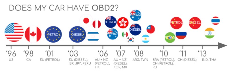
To determine if your car is OBD2 compliant, consider its origin and the year it was purchased new:
OBD2 Compliance Guide: This chart provides a general overview of OBD2 compliance based on vehicle origin and purchase year in the EU and US.
The History of OBD2 and Mandate Timeline
The story of OBD2 begins in California with the California Air Resources Board (CARB). Driven by the need for better emission control, CARB mandated OBD systems in all new cars sold in California starting from 1991. This initial OBD system was a precursor to the standardized OBD2 we know today.
The Society of Automotive Engineers (SAE) played a crucial role in standardizing the system. They recommended the OBD2 standard, which included standardized DTCs and a universal OBD connector (SAE J1962), ensuring consistency across different vehicle manufacturers.
From its Californian origins, the OBD2 standard gradually became mandatory across the United States and then globally:
- 1996: OBD2 Mandate in the USA for Cars and Light Trucks: This was a pivotal year. The United States Environmental Protection Agency (EPA) made OBD2 mandatory for all cars and light trucks sold in the USA. This regulation significantly pushed the adoption of OBD2 across the automotive industry.
- 2001: OBD2 Mandate in the European Union for Gasoline Cars (EOBD): The European Union followed suit, mandating OBD2, known as EOBD (European On-Board Diagnostics), for gasoline cars. This marked the spread of OBD2 regulations beyond North America.
- 2003: EOBD Mandate Extended to Diesel Cars in the EU: The EU expanded the EOBD mandate to include diesel cars as well, further strengthening the reach of on-board diagnostics for emissions control in Europe.
- 2005: OBD2 Required for Medium Duty Vehicles in the US: The US expanded the OBD2 mandate to medium-duty vehicles, encompassing a wider range of commercial vehicles.
- 2008: CAN Bus as Mandatory OBD2 Protocol in the US: A significant technical update occurred when the US mandated the ISO 15765-4 (CAN) protocol as the foundation for OBD2 communication. This standardized the communication method, improving interoperability.
- 2010: OBD2 Mandate for Heavy Duty Vehicles in the US: Finally, the OBD2 mandate in the US was completed with its extension to heavy-duty vehicles, ensuring comprehensive coverage across vehicle types.
OBD2 History and Emission Control: The timeline illustrates the evolution of OBD2, highlighting its origins in emission control and its global expansion.
OBD2 History Timeline: A visual timeline summarizing the key milestones in OBD2 history, from its Californian origins to global mandates.
The Future of OBD: OBD is evolving towards OBD3, incorporating remote diagnostics, cloud connectivity, and IoT integration for enhanced vehicle monitoring.
The Future of OBD2: Trends and Innovations
While OBD2 is firmly established, it continues to evolve. Here are some important trends shaping its future:
Electric Vehicles (EVs) and OBD2: Interestingly, the original legislative intent of OBD2 was primarily for emissions control. As a result, electric vehicles are not strictly required to support OBD2 in the same way as internal combustion engine vehicles. In practice, most modern EVs do not support standard OBD2 requests. Instead, they often use OEM-specific UDS (Unified Diagnostic Services) communication protocols. This makes accessing data from EVs more challenging, often requiring reverse engineering to decode proprietary data formats. However, there are ongoing efforts to improve access to EV data, as demonstrated by case studies for brands like Tesla, Hyundai/Kia, Nissan, and VW/Skoda.
Advanced OBD Protocols: WWH-OBD and OBDonUDS: Recognizing the limitations of current OBD2 in terms of data richness and protocol flexibility, newer alternatives have emerged. WWH-OBD (World Wide Harmonized OBD) and OBDonUDS (OBD on UDS) aim to modernize OBD communication by utilizing the UDS protocol as a foundation. These protocols offer enhanced capabilities and standardization.
OBD3 and Telematics: In the age of connected cars, manual emission checks are becoming increasingly inefficient. OBD3 is envisioned as a solution, integrating telematics into all vehicles. This concept involves adding a small radio transponder to cars, enabling wireless transmission of the vehicle identification number (VIN) and DTCs to a central server for automated monitoring. While this offers convenience and cost savings, it also raises privacy concerns related to data surveillance. Devices like the CANedge2 and CANedge3 already facilitate data transfer via WiFi or cellular networks, paving the way for OBD3-like functionalities.
Data Access Control and Security: The increasing use of OBD2 for third-party data access has sparked debate. While originally intended for repair shops, OBD2 is now used extensively by third-party services to gather real-time vehicle data. However, some automotive manufacturers are seeking to limit this access, proposing to “turn off” OBD2 functionality during driving and centralize data collection. Arguments for this include security improvements (reducing car hacking risks) and control over “automotive big data.” This trend could significantly impact the market for OBD2-based third-party services.
Future Challenges for OBD2: Electric vehicles are presenting new challenges as many block direct access to data via standard OBD2 protocols.
Enhance Your CAN Bus Expertise
Want to deepen your understanding of CAN bus technology?
Our comprehensive 160+ page PDF guide offers 12 simple introductions to CAN bus concepts.
Download now
OBD2 Standards: Defining the Framework
OBD2 operates as a higher-layer protocol on top of communication methods like CAN bus. Think of OBD2 as the language and CAN bus as the communication channel. This is similar to other CAN-based protocols like J1939, CANopen, and NMEA 2000.
OBD2 standards define various aspects, including the OBD2 connector, lower-layer protocols, and OBD2 parameter IDs (PIDs). These standards are often structured using the 7-layer OSI model, with both SAE (US standards) and ISO (EU standards) contributing. Many SAE and ISO standards are technically equivalent, such as SAE J1979 and ISO 15031-5 (for diagnostic services) and SAE J1962 and ISO 15031-3 (for the OBD connector).
OBD2 and CAN Bus in the OSI Model: This diagram illustrates how OBD2 and CAN bus relate within the 7-layer OSI model, highlighting relevant ISO and SAE standards.
OBD2 Connector Pinout (Type A): A detailed pinout diagram of a Type A OBD2 connector, also known as a Data Link Connector (DLC).
The OBD2 Connector [SAE J1962 / ISO 15031-3]
The 16-pin OBD2 connector is your physical interface to your vehicle’s diagnostic data. Standardized under SAE J1962 and ISO 15031-3, this connector provides easy access to vehicle information.
Key features of the OBD2 connector include:
- Location: Usually near the steering wheel, though sometimes hidden.
- Pin 16: Provides battery power, often even when the ignition is off.
- Pinout Variability: The specific pinout depends on the communication protocol used.
- CAN Bus Connection: In CAN bus systems, pins 6 (CAN-H) and 14 (CAN-L) are typically connected.
OBD2 Connector Types: A vs. B
You might encounter two main types of OBD2 connectors: Type A and Type B. Type A is most common in cars, while Type B is frequently used in medium and heavy-duty vehicles.
While both types share similar pinouts, they differ in:
- Power Supply: Type A provides 12V, while Type B provides 24V.
- Baud Rate: Cars (Type A) often use 500K baud rate, while heavy-duty vehicles (Type B) typically use 250K (with increasing support for 500K).
Physically, Type B connectors have an interrupted groove in the middle, distinguishing them from Type A. A Type B OBD2 adapter cable is generally compatible with both Type A and Type B sockets, but a Type A adapter will not fit into a Type B socket.
OBD2 Connector Types A and B: A comparison of Type A and Type B OBD2 connectors, highlighting differences in power supply and typical vehicle applications.
OBD2 and CAN Bus Relationship: Illustrating the relationship between OBD2 as a protocol and CAN bus as the underlying communication network, as defined by ISO 15765.
OBD2 and CAN Bus [ISO 15765-4]: Communication Foundation
Since 2008, CAN bus has been mandated as the lower-layer protocol for OBD2 in all US vehicles according to ISO 15765. ISO 15765-4, also known as Diagnostics over CAN (DoCAN), builds upon the CAN standard (ISO 11898) by adding specific constraints and specifications for diagnostic communication.
ISO 15765-4 standardizes the CAN interface for diagnostic equipment, focusing on:
- Bit-rate: Must be 250K or 500K.
- CAN IDs: Supports 11-bit and 29-bit CAN identifiers.
- Specific CAN IDs: Defined for OBD requests and responses.
- Data Length: Diagnostic CAN frames must have a data length of 8 bytes.
- Cable Length: OBD2 adapter cables are limited to a maximum length of 5 meters.
OBD2 CAN Identifiers: 11-bit and 29-bit
OBD2 communication relies on request/response message exchanges.
11-bit CAN Identifiers: Commonly used in cars for OBD2.
- Functional Addressing ID: 0x7DF – Used to query all OBD2-compatible ECUs for data related to a specific parameter.
- Physical Addressing IDs: 0x7E0-0x7E7 – Used for direct requests to specific ECUs (less frequent).
- Response IDs: 0x7E8-0x7EF – ECUs respond using these IDs. 0x7E8 (ECM – Engine Control Module) and 0x7E9 (TCM – Transmission Control Module) are typical response IDs.
29-bit CAN Identifiers: Found in some vehicles, especially vans and medium/heavy-duty vehicles.
- Functional Addressing CAN ID: 0x18DB33F1.
- Response IDs: 0x18DAF100 to 0x18DAF1FF (common examples: 0x18DAF110 and 0x18DAF11E).
- J1939 PGN: Response ID sometimes presented as PGN 0xDA00 (55808), which is reserved for ISO 15765-2 in the J1939-71 standard.
OBD2 Request and Response Frames: Illustrating the structure of OBD2 request and response frames, including Mode, PID, and data parameters.
OBD2 vs. Proprietary CAN Bus Data: Contrasting OBD2 data, which is standardized and accessible, with OEM-specific CAN bus data, which is proprietary and often requires reverse engineering to understand.
OBD2 vs. Proprietary CAN Protocols
It’s important to understand that OBD2 is an additional protocol, separate from the OEM-specific CAN protocols used for the vehicle’s core functions. Vehicle ECUs don’t rely on OBD2 for their primary operations. Each manufacturer implements their own proprietary CAN protocols, which are often specific to vehicle brand, model, and year. This OEM-specific data is generally not interpretable without reverse engineering.
When connecting a CAN bus data logger to the OBD2 port, you might observe OEM-specific CAN data alongside OBD2 data. However, in many newer vehicles, a gateway module restricts access to OEM-specific CAN data through the OBD2 port, allowing only OBD2 communication.
Essentially, OBD2 functions as a parallel, higher-layer protocol alongside the OEM-specific communication network.
Bit-rate and ID Validation: Establishing Communication
OBD2 can operate with two bit-rates (250K, 500K) and two CAN ID lengths (11-bit, 29-bit), resulting in four potential combinations. Modern cars commonly use 500K and 11-bit IDs, but diagnostic tools should systematically verify these parameters.
ISO 15765-4 provides a recommended initialization sequence to determine the correct combination. This process relies on the fact that OBD2-compliant vehicles must respond to a mandatory OBD2 request (specifically, mode 0x01 PID 0x00) and that incorrect bit-rate transmission will cause CAN error frames.
Newer versions of ISO 15765-4 also consider OBDonUDS as an alternative to OBDonEDS (OBD on Emission Diagnostic Service). While OBDonEDS (also known as OBD2, SAE OBD, EOBD, or ISO OBD) is prevalent in most non-EV cars, WWH-OBD/OBDonUDS is primarily used in EU trucks and buses. To differentiate between these protocols, diagnostic tools may send UDS requests with specific service and data identifier (DID) codes.
OBD2 Bit-rate and CAN ID Validation Flowchart: A flowchart illustrating the systematic process for validating the correct bit-rate and CAN ID configuration for OBD2 communication, as per ISO 15765-4.
Five Lower-Layer OBD2 Protocols: An overview of the five primary lower-layer protocols used for OBD2 communication, including CAN (ISO 15765) and legacy protocols like KWP2000 and SAE J1850.
Five Lower-Layer OBD2 Protocols: Beyond CAN
While CAN bus (ISO 15765) is dominant in modern vehicles, particularly post-2008, older cars might utilize other lower-layer protocols for OBD2. Understanding these legacy protocols can be helpful when working with older vehicles. The five primary lower-layer OBD2 protocols are:
- ISO 15765 (CAN bus): Mandatory in US cars since 2008 and the most prevalent protocol today.
- ISO 14230-4 (KWP2000): Keyword Protocol 2000, common in 2003+ vehicles, especially in Asia.
- ISO 9141-2: Used in EU, Chrysler, and Asian cars from 2000-2004.
- SAE J1850 (VPW): Primarily used in older GM vehicles.
- SAE J1850 (PWM): Primarily used in older Ford vehicles.
ISO-TP: Transporting OBD2 Messages [ISO 15765-2]
OBD2 data transmission over CAN bus relies on the ISO-TP (ISO 15765-2) transport protocol. ISO-TP enables the transmission of data payloads exceeding the 8-byte limit of a single CAN frame. This is essential for OBD2 functions like retrieving the Vehicle Identification Number (VIN) or Diagnostic Trouble Codes (DTCs), which often require larger data packets. ISO-TP handles segmentation, flow control, and reassembly of these larger messages.
For smaller OBD2 data transmissions that fit within a single CAN frame, ISO 15765-2 specifies the use of ‘Single Frame’ (SF) messages. In a Single Frame, the first data byte (PCI field) indicates the payload length (excluding padding), leaving 7 bytes for OBD2-related data.
ISO-TP Frame Types for OBD2: An overview of the different frame types defined by ISO-TP (ISO 15765-2) for OBD2 communication, including Single Frame, First Frame, Consecutive Frame, and Flow Control Frame.
The OBD2 Diagnostic Message [SAE J1979, ISO 15031-5]: Structure and Components
To understand OBD2 communication, let’s examine the structure of a raw ‘Single Frame’ OBD2 CAN message. In simplified terms, an OBD2 message consists of:
- Identifier (CAN ID): Indicates the message’s source and destination.
- Data Length (PCI field): Specifies the length of the data payload.
- Data Payload: Contains the actual OBD2 information, broken down into:
- Mode (Service): Defines the type of diagnostic service being requested or provided.
- Parameter ID (PID): Identifies the specific parameter being requested or reported.
- Data Bytes: Contain the actual data values for the requested parameter.
OBD2 Message Structure Breakdown: A detailed breakdown of the components within an OBD2 message, highlighting the Mode, Parameter ID (PID), and data bytes.
OBD2 Request/Response Example: Vehicle Speed
Consider a practical example: requesting and receiving vehicle speed data.
- Request: An external tool sends a request message with CAN ID 0x7DF and 2 payload bytes: Mode 0x01 and PID 0x0D.
- Response: The car responds with a message using CAN ID 0x7E8 and 3 payload bytes. The vehicle speed value is contained in the 4th byte, 0x32 (which is 50 in decimal).
By consulting the OBD2 PID documentation for PID 0x0D, we can determine that the value 0x32 corresponds to a vehicle speed of 50 km/h.
OBD2 Request and Response Example (Vehicle Speed): Illustrating a request for vehicle speed (PID 0x0D) and the corresponding response, showing the CAN IDs and data payload.
OBD2 PID 0x0D (Vehicle Speed) Details: Specifics of OBD2 PID 0x0D, which is used to request and receive vehicle speed data.
OBD2 Services (Modes) Overview: A summary of the 10 standardized OBD2 services or modes, including services for real-time data, DTCs, and freeze frame information.
The 10 OBD2 Services (Modes)
OBD2 defines 10 diagnostic services, also referred to as modes. Mode 0x01 is used for retrieving current real-time data, while other modes are used for accessing and clearing diagnostic trouble codes (DTCs) or retrieving freeze frame data.
Not all OBD2 modes are mandatory, and vehicles may also support OEM-specific modes beyond the 10 standardized ones.
In OBD2 messages, the mode is located in the second byte of the data payload. In a request message, the mode is included directly (e.g., 0x01). In a response message, 0x40 is added to the requested mode value (e.g., a response to mode 0x01 will have mode value 0x41).
OBD2 Parameter IDs (PIDs): Accessing Specific Data
Within each OBD2 mode, Parameter IDs (PIDs) are used to identify specific data points. For example, Mode 0x01 contains approximately 200 standardized PIDs providing real-time data on parameters like speed, RPM, and fuel level. However, vehicles are not required to support all PIDs within a mode, and most vehicles only support a subset of the available PIDs.
PID 0x00 in Mode 0x01 is a special case. If an emissions-related ECU supports any OBD2 services, it must support Mode 0x01 PID 0x00. When queried with PID 0x00, the ECU responds by indicating which PIDs from 0x01 to 0x20 it supports. This makes PID 0x00 a fundamental tool for testing OBD2 compatibility. Similarly, PIDs 0x20, 0x40, 0x60, 0x80, 0xA0, and 0xC0 are used to determine support for subsequent PID ranges within Mode 0x01.
(Repeated Image) OBD2 Request and Response Frames: Illustrating the structure of OBD2 request and response frames, including Mode, PID, and data parameters.
OBD2 PID Overview Tool: A screenshot of an OBD2 PID overview tool, designed to help users explore and understand OBD2 PIDs and their functionalities.
OBD2 PID Overview Tool: Your Decoding Aid
The appendices of SAE J1979 and ISO 15031-5 provide scaling information for standard OBD2 PIDs, which is essential for converting raw data values into physical units.
For easy lookup of Mode 0x01 PIDs, utilize our OBD2 PID overview tool. This tool assists in constructing OBD2 request frames and dynamically decoding OBD2 responses, simplifying the process of accessing and interpreting OBD2 data.
OBD2 PID overview tool
Logging and Decoding OBD2 Data: A Practical Guide
Let’s walk through a practical example of logging OBD2 data using the CANedge CAN bus data logger. The CANedge allows custom CAN frame transmission, making it suitable for OBD2 data logging. Connect the CANedge to your vehicle using an OBD2-DB9 adapter cable.
OBD2 Data Logger Setup: Illustrating the setup of an OBD2 data logger, showing the connection to the OBD2 port and the CAN bus network.
Supported PIDs Test Results: A view in asammdf software displaying the responses received during a test to identify supported OBD2 PIDs.
Step #1: Bit-rate, ID, and Supported PID Testing
ISO 15765-4 outlines how to determine the correct bit-rate and CAN IDs for a specific vehicle. You can use the CANedge to perform these tests:
- Bit-rate Test: Transmit a CAN frame at 500K. If successful, use 500K. Otherwise, try 250K.
- Subsequent Communication: Use the identified bit-rate for all further communication.
- Supported PIDs Request: Send multiple ‘Supported PIDs’ requests (Mode 0x01, PID 0x00) and analyze the responses.
- CAN ID Determination: Response IDs (0x7E8-0x7EF for 11-bit, 0x18DAF1xx for 29-bit) indicate 11-bit or 29-bit CAN IDs.
- Supported PID Identification: Response data reveals the PIDs supported by the vehicle.
Pre-configured CANedge settings are available to simplify these tests. Most post-2008 non-EV cars typically support 40-80 PIDs, using 500K bit-rate, 11-bit CAN IDs, and the OBD2/OBDonEDS protocol.
Analyzing responses in software like asammdf reveals multiple responses to a single OBD request (due to the use of the functional address 0x7DF, which queries all ECUs). The ECM (0x7E8) often supports all PIDs supported by other ECUs, allowing for reduced bus load by directly addressing the ECM using physical addressing CAN ID 0x7E0 for subsequent requests.
Step #2: Configuring OBD2 PID Requests
Once you know the supported PIDs, bit-rate, and CAN IDs, configure your data logger to request the PIDs you are interested in.
Consider these points for configuration:
- CAN IDs: Use ‘Physical Addressing’ request IDs (e.g., 0x7E0) to target specific ECUs and minimize multiple responses.
- Request Spacing: Introduce a delay of 300-500 ms between OBD2 requests to prevent ECU overload.
- Battery Management: Implement triggers to stop data transmission when the vehicle is inactive to avoid battery drain.
- Data Filtering: Apply filters to record only OBD2 responses if OEM-specific CAN data is also present.
With these configurations, your CANedge is ready to log raw OBD2 data.
CANedge OBD2 Request Configuration: An example configuration for a CANedge data logger, showing a list of OBD2 PID requests set up for data logging.
Decoded OBD2 Data Visualization: A screenshot from asammdf software showing decoded and visualized OBD2 data, plotted using a DBC file for signal interpretation.
Step #3: DBC Decoding of Raw OBD2 Data
To analyze and visualize logged OBD2 data, you need to decode the raw data into physical values. Decoding information is available in ISO 15031-5/SAE J1979 and online resources like Wikipedia. For convenience, a free OBD2 DBC file is provided to facilitate DBC decoding in most CAN bus software tools.
Decoding OBD2 data is more complex than standard CAN signal decoding because multiple OBD2 PIDs are transmitted using the same CAN ID (e.g., 0x7E8). Therefore, the CAN ID alone is insufficient to identify the signals. ‘Extended multiplexing’ is used, where both the CAN ID, OBD2 mode, and OBD2 PID are necessary to uniquely identify and decode the signal. This multiplexing approach is implemented in the provided DBC file.
CANedge: Your OBD2 Data Logging Solution
The CANedge offers a streamlined solution for recording OBD2 data directly to an SD card (8-32 GB). Simply connect the CANedge to your vehicle to start logging, and then use free software and APIs along with our OBD2 DBC file to decode the collected data.
OBD2 logger intro CANedge
OBD2 Multi-Frame Examples [ISO-TP]: VIN, Multi-PID, and DTCs
While single-frame communication is common in OBD2, multi-frame communication using ISO-TP is necessary for larger data requests and responses. Multi-frame communication involves flow control frames. A common approach is to transmit a static flow control frame approximately 50 ms after the initial request frame. Software tools like CANedge MF4 decoders are required to handle multi-frame OBD2 responses.
OBD2 Multi-Frame Request Example: Illustrating an OBD2 multi-frame request message, specifically for requesting the Vehicle Identification Number (VIN).
Example 1: OBD2 Vehicle Identification Number (VIN) Retrieval
The Vehicle Identification Number (VIN) is crucial for telematics, diagnostics, and vehicle identification. To retrieve the VIN using OBD2, use Mode 0x09 and PID 0x02.
- Request: A Single Frame request is sent with PCI field (0x02), service ID (0x09), and PID (0x02).
- Response: The vehicle responds with a multi-frame sequence:
- First Frame: Contains PCI, length (total bytes in the multi-frame message), mode (0x49), PID (0x02), Number Of Data Items (NODI – typically 1 for VIN), and the first part of the VIN.
- Consecutive Frames: Contain the remaining bytes of the VIN.
The VIN, typically 17 bytes, is encoded in HEX and can be converted to ASCII to obtain the readable VIN string.
Example 2: OBD2 Multi-PID Request (6x)
OBD2 allows requesting up to 6 Mode 0x01 PIDs in a single request frame. The ECU will respond with data for the supported PIDs in a multi-frame response if necessary. While efficient for data collection, this method complicates data decoding, especially with generic OBD2 DBC files. It’s generally not recommended for practical logging unless tools with specific multi-PID support are used.
The multi-frame response structure is similar to the VIN example, but the payload includes the requested PIDs along with their corresponding data. Decoding this type of response using generic DBC files is challenging due to the complex multiplexing and PID ordering.
Example 3: OBD2 Diagnostic Trouble Codes (DTCs)
OBD2 Mode 0x03 is used to request emissions-related Diagnostic Trouble Codes (DTCs). The request does not include a PID. The ECU responds with the number of stored DTCs and the DTC codes themselves, each DTC being 2 bytes. Multi-frame responses are needed when more than 2 DTCs are stored.
The 2-byte DTC value is structured into a category and a 4-digit code. DTC values can be decoded using OBD2 DTC lookup tools.
OBD2 DTC Decoding Example: Illustrating how 2-byte DTC values are structured and decoded, showing the category and 4-digit code breakdown.
The example trace shows a request to an ECU with 6 stored DTCs.
OBD2 Data Logging: Use Case Applications
OBD2 data logging has diverse applications across various sectors:
OBD2 Data Logging Applications: Visual representation of various applications for OBD2 data logging in vehicles, including performance monitoring and diagnostics.
Car Data Logging: Performance and Efficiency
OBD2 data from cars is valuable for:
- Fuel Efficiency Improvement: Analyzing driving habits and vehicle parameters to optimize fuel consumption.
- Driving Behavior Analysis: Monitoring driving style for safety and training purposes.
- Prototype Testing: Evaluating new automotive components and systems.
- Insurance Telematics: Usage-based insurance models and accident reconstruction.
obd2 logger
OBD2 Real-time Streaming Diagnostics: Illustrating real-time OBD2 data streaming for vehicle diagnostics and monitoring.
Real-time Car Diagnostics: Immediate Insights
OBD2 interfaces enable real-time streaming of human-readable data for:
- Vehicle Issue Diagnosis: Quickly identifying and troubleshooting vehicle malfunctions.
- Live Performance Monitoring: Displaying real-time engine and vehicle parameters.
obd2 streaming
OBD2 Predictive Maintenance: OBD2 data used for predictive maintenance, leveraging IoT and cloud connectivity to anticipate vehicle issues.
Predictive Maintenance: Proactive Vehicle Care
Cloud-connected OBD2 loggers facilitate:
- Predictive Maintenance: Monitoring vehicle health remotely to predict and prevent breakdowns.
- Fleet Management: Tracking vehicle performance and maintenance needs across fleets.
predictive maintenance
OBD2 Black Box Logging: OBD2 data logger functioning as a ‘black box’ recorder for vehicles, capturing data for insurance and diagnostic purposes.
Vehicle Black Box Logging: Data for Accountability
OBD2 loggers serve as ‘black boxes’ for:
- Incident Analysis: Providing data for accident investigation and dispute resolution.
- Warranty Validation: Verifying vehicle operating conditions for warranty claims.
can bus blackbox
Do you have an OBD2 data logging application in mind? Contact us for expert guidance!
Contact us
Explore our guides for more introductory articles, or download the ‘Ultimate Guide’ PDF for in-depth CAN bus knowledge.
Ready to start logging and streaming OBD2 data?
Get your OBD2 data logger today!
Buy now Contact us
Further Reading Recommendations
OBD2 DATA LOGGER: EASILY LOG & CONVERT OBD2 DATA
CANEDGE2 – PRO CAN IoT LOGGER
[