For car enthusiasts and DIY mechanics, accessing your vehicle’s diagnostic data is invaluable. While off-the-shelf OBD2 scanners are readily available, sometimes you need a more customized connection, especially when working with specific systems or older interfaces. This guide will walk you through the process of creating your own OBD2 to 4-pin diagnostic cable, allowing for a direct connection to various diagnostic tools and systems. Please note, this project is for informational purposes and should be undertaken at your own risk. Incorrect wiring can damage your vehicle’s electronics.
Tools and Parts You’ll Need
Before you begin, gather the necessary tools and parts. Having everything prepared will make the process smoother and more efficient.
- Wire strippers/cutters: Essential for preparing the wires for connection.
- Needle-nose pliers: Helpful for manipulating small parts and wires, especially when crimping connectors.
- Molex crimping tool (optional but recommended): A crimping tool ensures a secure and professional connection between wires and connector pins. While pliers can be used, a crimping tool provides a more reliable result.
- Soldering iron (recommended): Soldering provides a robust and electrically sound connection, especially for finer wires. It adds an extra layer of security to your connections.
- 4-pin connector kit: This connector will serve as the interface to your diagnostic tool or system. Ensure it’s compatible with your intended use.
- OBD-II Cable: This cable provides the OBD2 connector that plugs into your vehicle’s diagnostic port.
You can source these parts from electronic component suppliers online. For the connectors, consider options like those from Corsa Technic, which offer reliable automotive connectors.
Understanding the OBD2 Connector and Wiring
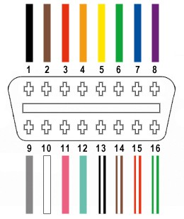
The OBD2 connector is a standardized 16-pin interface in modern vehicles, but for many DIY diagnostic applications, you only need to tap into a few key pins. For this cable, we will focus on the essential pins for basic CAN bus communication, which is commonly used in automotive diagnostics.
Out of the 16 pins on the OBD2 connector (OBD2C), we will be utilizing these four:
- Pin 4: Chassis Ground (Ground connection for the circuit)
- Pin 6: CAN High (CAN bus high signal line)
- Pin 14: CAN Low (CAN bus low signal line)
- Pin 16: Battery Power (12V power supply)
These four pins are sufficient for establishing a basic connection for reading diagnostic data and communicating with your vehicle’s systems.
Step-by-Step Guide to Building Your OBD2 to 4-Pin Cable
Let’s get started with the construction process. Follow these steps carefully to assemble your cable.
Step 1: Prepare the OBD2 Cable Wires
Begin by preparing the OBD2 cable. Carefully remove the outer sheath and shielding from the end of the OBD2 cable to expose the individual wires inside. Identify the wires connected to pins 4, 6, 14, and 16. These are the wires we will be working with. In the example OBD2 cable, these wires are:
- Pin 4 (Chassis ground): Orange wire
- Pin 6 (CAN High): Green wire
- Pin 14 (CAN Low): Brown wire with white stripe
- Pin 16 (Battery power): Green wire with white stripe
Once identified, carefully separate these four wires from the rest of the wires in the OBD2 cable and neatly bundle the remaining wires to keep them out of the way. You can use a zip tie to secure the unused wires.
Step 2: Prepare the Wires for the 4-Pin Connector
The wires in the OBD2 cable are often very thin (26AWG in this example), and the pins for the 4-pin connector are designed for slightly thicker wires (22-16AWG). To ensure a good connection, we need to thicken the ends of the OBD2 wires.
Carefully strip about 3/8″ of insulation from the ends of each of the four selected OBD2 wires. Fold the exposed wire strands back over the insulation to double the thickness and then twist the strands together tightly. This will make the wire thicker and better suited for the 4-pin connector pins. Slide a rubber seal (from the 4-pin connector kit) onto each wire. These seals will provide environmental protection for the connections.
Step 3: Attach Wires to 4-Pin Connector Pins
Now, take the pins from the 4-pin connector kit. Each pin has two sets of prongs. The front set of prongs is designed to crimp onto the wire itself, and the rear set is for crimping onto the wire insulation/seal.
Insert the prepared wire into the front of a pin, ensuring the exposed wire aligns with the front prongs. Use needle-nose pliers to hold the wire in place against the pin connector.
Step 4: Soldering (Recommended) or Crimping the Wires
Soldering (Recommended): Soldering provides a more secure and reliable connection, especially with the thin wires used in OBD2 cables. If you choose to solder, apply a small amount of solder to the area where the wire meets the front prongs of the connector pin. Ensure the solder flows smoothly and creates a solid joint. Be careful not to use excessive solder.
Crimping (Alternative): If you have a Molex crimping tool, use it to crimp the front prongs of the connector pin firmly onto the wire. If you don’t have a crimping tool, you can carefully use needle-nose pliers. Fold one prong at a time over the wire, squeezing gently but firmly to create a secure mechanical connection.
Step 5: Crimp the Seal and Finalize Pin Connection
Slide the rubber seal up the wire until it sits between the rear set of prongs on the connector pin. Use your crimping tool or needle-nose pliers to fold these rear prongs over the rubber seal. This secures the seal in place and provides strain relief for the wire. Repeat steps 3-5 for the remaining three wires and connector pins.
Step 6: Wire Pairing (Recommended for CAN Bus)
For CAN bus communication, it’s often recommended to twist the CAN High and CAN Low wires together, as well as the Power and Ground wires. This helps to reduce electromagnetic interference and improve signal integrity.
Pair the wires as follows and twist each pair together:
- Pin 4 (Orange – Ground) and Pin 16 (Green w/white stripe – Power)
- Pin 6 (Green – CAN High) and Pin 14 (Brown w/white stripe – CAN Low)
Step 7: Insert Pins into the 4-Pin Connector Housing
Finally, insert the completed pins into the 4-pin connector housing in the correct order. The standard pinout for many 4-pin diagnostic connectors is as follows (verify the pinout for your specific diagnostic tool):
- Slot A: Pin 14 (Brown w/white stripe – CAN Low)
- Slot B: Pin 6 (Green – CAN High)
- Slot C: Pin 16 (Green w/white stripe – Power)
- Slot D: Pin 4 (Orange – Ground)
Insert each pin into the back of the connector housing until it clicks into place. You should hear or feel a click indicating that the pin is locked. You can use needle-nose pliers to gently pull on the wire from the rear to ensure the pin is securely locked in the connector.
Testing Your DIY OBD2 to 4-Pin Cable
Congratulations, you’ve built your own OBD2 to 4-pin diagnostic cable! Before using it on your vehicle, double-check all your connections and wiring against the pinout diagrams.
When you are ready to test, connect the OBD2 end to your vehicle’s OBD2 port and the 4-pin connector to your diagnostic tool or system. Power on your diagnostic equipment and attempt to connect to your vehicle’s ECU. If everything is wired correctly, you should be able to read diagnostic data, check for error codes, and perform other diagnostic functions as supported by your tool and vehicle.
Disclaimer: This guide is for informational purposes only. Building and using this cable is done at your own risk. Incorrect wiring can damage your vehicle’s electronic systems. If you are not comfortable with automotive wiring and electronics, it is recommended to consult with a professional. Always refer to your vehicle’s service manual and the documentation for your diagnostic tools for specific instructions and safety precautions.