Disclaimer: I am not a professional, just a DIY enthusiast who has successfully performed this procedure. This guide is based on my personal experience, and while I hope it works for you, I am not responsible for any outcomes. Modifying your car’s electrical system carries risks. Proceed at your own risk. Potential issues could include a malfunctioning harness, damage to your ECU, or unexpected consequences.
Creating your own OBD2 connector can be a useful skill for automotive diagnostics and custom projects. This guide will walk you through the process of building a simple OBD2 connector using readily available parts. This DIY approach can save you money and provide a deeper understanding of your vehicle’s diagnostic system.
Tools You’ll Need
- Wire strippers/cutters
- Needle-nose pliers
- Soldering iron (recommended for a secure connection)
- Molex crimping tool (optional, but helpful for crimping pins)
Parts Required
- 4-Pin Connector (Corsa Technic 4-Pin Connector; suitable for 22-16AWG wire, 1.3-1.7mm insulation)
- OBD-II Cable (Corsa Technic OBD-II Cable)
Alternatively, to save on costs, you can purchase a female OBD-II connector separately and use your own 4-conductor wire to connect to the 4-pin connector. Ensure you select the correct 4-pin connector size to match your wire gauge.
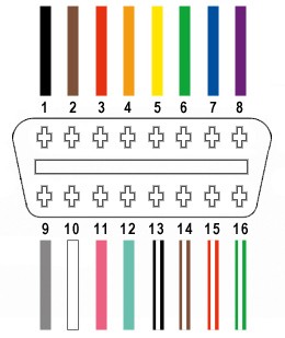
For this project, we will only be utilizing four wires from the OBD-II connector (OBD2C):
- Pin 4: Chassis Ground (Orange wire on OBD2C)
- Pin 6: CAN (J-2234) High (Green wire on OBD2C)
- Pin 14: CAN (J-2234) Low (Brown w/white stripe wire on OBD2C)
- Pin 16: Battery Power (Green w/white stripe wire on OBD2C)
Step-by-Step Guide to Building Your OBD2 Connector
1. Wire Preparation
Begin by preparing the OBD-II cable. Carefully remove the outer sheath and shielding from the OBD2C to expose the individual wires. Identify and separate the four wires you will be using (Pin 4, 6, 14, and 16 as listed above). Bundle the remaining 12 wires and secure them out of the way using a zip tie. This keeps your workspace tidy and prevents accidental connections.
2. Pin Attachment
The wires in the OBD2C are 26AWG, which are slightly smaller than the 22AWG size recommended for the pins of the 4-pin connector (4PC). To ensure a secure connection, we need to thicken the wire ends. The wires come pre-stripped with a small amount of exposed wire. Strip off approximately 3/8″ of insulation. Fold the exposed wire over itself, twisting the strands to increase its thickness and improve contact with the pin. Slide a rubber seal from the 4PC kit onto each of the four prepared wires.
3. Connector Pin Crimping and Soldering
Examine the pins for the 4PC. You’ll notice two sets of prongs. The front prongs are designed to crimp onto the exposed wire, while the rear prongs crimp onto the wire seal. Insert the prepared wire into the pin, ensuring the exposed wire aligns with the front prongs. Due to the small wire gauge, soldering is highly recommended to create a robust electrical and mechanical connection. Solder the wire to the pin. If you are new to soldering, numerous online resources like YouTube tutorials can provide helpful guidance.
4. Crimping (Alternative to Soldering)
If you prefer crimping and have a Molex crimping tool, align the front prongs of the pin over the wire. Use the crimping tool to carefully fold these prongs over, securing the wire. If you don’t have a crimping tool, needle-nose pliers can be used. Angle the pliers and gently squeeze one prong at a time to fold it over the wire. Take your time to ensure a tight crimp. For added security, you can further flatten the crimped prongs with pliers.
5. Securing the Seal and Final Pin Crimping
Slide the rubber seal up the wire until it sits between the rear set of prongs on the pin. Using the same crimping technique (either with a crimping tool or needle-nose pliers), fold the rear prongs over the rubber seal. This provides strain relief and environmental protection to the connection.
6. Wire Pairing (Recommended)
While not definitively proven to be necessary, many DIY guides recommend twisting pairs of wires to minimize electromagnetic interference. Pair and twist the wires as follows:
- Pin 4 (Orange) & Pin 16 (Green w/white stripe) – Power pair
- Pin 6 (Green) & Pin 14 (Brown w/white stripe) – CAN Bus pair
7. Connector Assembly
Insert the completed pins into the 4-pin connector housing (4PC) in the correct orientation as shown below:
- Slot A: Pin 14 (Brown w/white stripe) – CAN Low
- Slot B: Pin 6 (Green) – CAN High
- Slot C: Pin 16 (Green w/white stripe) – Battery Power
- Slot D: Pin 4 (Orange) – Chassis Ground
Push each pin into the rear of the connector until you hear a distinct “click,” indicating it is locked securely in place. Using needle-nose pliers from the front of the connector can sometimes aid in pulling the pin fully into its locked position.
Testing Your DIY OBD2 Connector
Congratulations! Your DIY OBD2 connector is now complete.
Before using your new connector for critical tasks, test it in a safe and controlled environment. A simple test involves connecting it to your vehicle and using an OBD2 scanner to check for and clear any diagnostic trouble codes.
By following these steps, you can successfully create your own OBD2 connector for various automotive diagnostic and DIY projects. Remember to double-check all connections and proceed cautiously when working with your vehicle’s electrical system.