Are you looking to perform your own car diagnostics but finding the right equipment a bit pricey? Or perhaps you’re a hands-on enthusiast who enjoys a good DIY project? Creating your own Obd2 Adapter Cable can be a rewarding and cost-effective solution. This guide will walk you through the process of building a simple OBD2 adapter cable, perfect for basic diagnostic tasks. Please remember, this is a DIY project and should be undertaken at your own risk. We are not responsible for any damage that may occur.
Tools and Parts You’ll Need
Before you start, gather these essential tools and parts:
- Wire strippers/cutters: For preparing the wires.
- Needle-nose pliers: Helpful for handling small components.
- Molex crimping tool (optional): Recommended for professional crimping, but pliers can be used.
- Soldering iron (recommended): For a more secure and reliable connection.
- 4-Pin Connector: This connector will interface with your diagnostic tool. (Link to a suitable 4-pin connector part; suitable for 22-16AWG wire, 1.3-1.7mm insulation)
- OBD-II Cable: Provides the OBD2 connector. (Link to a suitable OBD-II cable part)
If you have spare wires available, you can purchase just the female OBD-II connector and wire, potentially saving on costs. Ensure you choose the correct wire size to match the 4-pin connector for secure connections.
Understanding the OBD2 Wiring
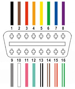
The OBD2 connector (OBD2C) has 16 pins, but for basic diagnostics, we only need to focus on four key connections:
- Pin 4: Chassis Ground (typically orange wire on the OBD2C)
- Pin 6: CAN High (CAN J-2234) (typically green wire on the OBD2C)
- Pin 14: CAN Low (CAN J-2234) (typically brown with white stripe wire on the OBD2C)
- Pin 16: Battery Power (typically green with white stripe wire on the OBD2C)
Step-by-Step Guide to Building Your OBD2 Adapter Cable
Let’s get started with the construction process:
1. Preparing the OBD2 Cable Wires:
Many guides recommend twisting pairs of wires to reduce interference. To facilitate this, carefully remove the outer sheath and shielding from the OBD2 cable. Isolate the four wires you’ll be using (Pins 4, 6, 14, and 16) and use a zip tie to bundle the remaining twelve wires out of your way.
2. Preparing the Wires for the 4-Pin Connector:
The wires in the OBD2 cable are often 26AWG, which is smaller than the 22AWG size intended for the 4-pin connector (4PC) pins. To compensate for this, carefully strip about 3/8″ of insulation from the end of each of the four wires. Fold the exposed wire over itself and twist it to increase its thickness, making it a better fit for the 4PC pins. Slide a rubber seal from the 4PC kit onto each wire.
3. Attaching Wires to 4-Pin Connector Pins:
The pins for the 4PC have two sets of prongs. The front prongs are for securing the wire, and the rear prongs are for the rubber seal. Insert the exposed wire into the front prongs of a pin. Due to the small wire size, using needle-nose pliers to hold the wire in place during the next step is helpful.
4. Soldering the Wires (Recommended):
Soldering provides a robust and reliable connection, especially beneficial given the small wire gauge. Solder the wire to the pin connector. If you’re new to soldering, numerous online tutorials, like this helpful YouTube video, can provide guidance.
5. Crimping the Connector (Alternative to Soldering):
If you have a Molex crimping tool, use it to crimp the connector prongs securely around the wire. If you don’t have this tool, needle-nose pliers can be used as an alternative. Carefully fold one prong at a time over the wire, ensuring a tight crimp. For added security, you can further compress the prongs with pliers.
6. Securing the Rubber Seal:
Slide the rubber seal up to the rear prongs of the pin. Use the same crimping technique with pliers to fold these prongs over the seal, securing it in place.
7. Wire Pairing and Twisting:
While not always essential, twisting wire pairs is often recommended to minimize interference. Pair and twist the wires as follows:
- Pin 4 (orange) with Pin 16 (green w/white stripe)
- Pin 6 (green) with Pin 14 (brown w/white stripe)
8. Inserting Pins into the 4-Pin Connector Housing:
Insert the prepared pins into the 4-Pin Connector (4PC) housing in the correct orientation, referring to the diagram below:
- Pin 14 (brown w/white stripe) > Connector Slot A
- Pin 6 (green) > Connector Slot B
- Pin 16 (green w/white stripe) > Connector Slot C
- Pin 4 (orange) > Connector Slot D
Push each pin into the rear of the connector until you hear a click, indicating it’s locked in place. Use needle-nose pliers to gently pull on each wire to ensure it is securely seated.
Testing Your DIY OBD2 Adapter Cable
Congratulations! Your DIY OBD2 adapter cable is now complete.
You can now test your cable by connecting it to your vehicle and a compatible OBD2 diagnostic tool. This DIY cable can be used to read and clear basic error codes, allowing you to troubleshoot common car issues.
This guide provides a basic approach to creating an OBD2 adapter cable. While it’s functional for many DIY diagnostic needs, remember that more complex diagnostic tasks might require professional-grade tools and cables. If you encounter any issues or have questions, consult online resources or experienced technicians.