As a content creator for obd-de.com and an expert in automotive repair, this guide provides an in-depth look into Obd2 Can Bus Messages. Building upon the original article, we aim to deliver a superior resource for understanding and utilizing OBD2, specifically focusing on its communication over the Controller Area Network (CAN bus). This article is optimized for an English-speaking audience interested in automotive diagnostics, repair, and data analysis.
What is OBD2 and its Connection to CAN Bus?
OBD2, or On-Board Diagnostics version 2, is your car’s essential self-diagnostic system. It’s a standardized protocol that allows access to crucial diagnostic trouble codes (DTCs) and real-time vehicle data through the OBD2 connector. This system is fundamental for modern vehicle maintenance and repair.
You’ve likely encountered OBD2 through the check engine light illuminating on your dashboard. This indicator signals an issue detected by your car’s internal systems. Mechanics use OBD2 scanners to interpret these signals and diagnose problems efficiently.
The process involves connecting an OBD2 reader to the 16-pin OBD2 connector, typically located near the steering wheel. This tool sends ‘OBD2 requests’ to the vehicle, which then responds with ‘OBD2 responses’. These responses contain valuable data such as speed, fuel level, and DTCs, enabling quicker and more accurate troubleshooting. A critical aspect of this communication is the transmission of obd2 can bus messages, which we will delve into.
Understanding the OBD2 system, including the malfunction indicator light (MIL) and scan tool, is crucial for modern vehicle diagnostics.
OBD2 Support: Is Your Car Compatible?
The answer is: Most likely, yes!
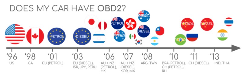
The vast majority of modern non-electric vehicles are OBD2 compliant, and a significant portion of these utilize CAN bus for communication. However, it’s important to note that the presence of a 16-pin OBD2 connector doesn’t guarantee OBD2 compliance, especially in older models. To confirm compatibility, consider the vehicle’s origin and purchase date:
A Brief History of OBD2
OBD2’s roots are in California, where the California Air Resources Board (CARB) mandated OBD for all new vehicles from 1991 onwards to monitor and control emissions.
The Society of Automotive Engineers (SAE) played a key role in standardizing OBD2, particularly in DTCs and the OBD connector, outlined in SAE J1962.
The OBD2 standard was progressively implemented across different regions and vehicle types:
- 1996: OBD2 became mandatory in the USA for cars and light trucks.
- 2001: Required in the EU for gasoline cars.
- 2003: Extended to diesel cars in the EU (known as EOBD).
- 2005: Required in the US for medium-duty vehicles.
- 2008: US vehicles mandated to use ISO 15765-4 (CAN) as the foundation for OBD2, standardizing obd2 can bus messages.
- 2010: OBD2 requirement extended to heavy-duty vehicles in the US.
The Future Trajectory of OBD2
OBD2 is expected to remain relevant, although its form and application are evolving. Key trends include:
Originally conceived for emission control and testing, legislated OBD2 faces a shift with electric vehicles. Electric vehicles (EVs) generally do not support OBD2 in its standard form. Most EVs utilize OEM-specific UDS communication protocols instead. This shift makes accessing data from EVs challenging without reverse-engineered solutions. However, resources are emerging for specific EV brands like Tesla, Hyundai/Kia, Nissan, and VW/Skoda.
Considering the limitations of current OBD2 implementations in data richness and lower-layer protocols, modern alternatives like WWH-OBD (World Wide Harmonized OBD) and OBDonUDS (OBD on UDS) are being developed. These aim to enhance OBD communication by using the UDS protocol as a base. For more information, refer to our introduction to UDS.
In the era of connected cars, manual OBD2 emission tests are becoming less efficient. OBD3 proposes integrating telematics into all vehicles. OBD3 envisions adding a radio transponder to vehicles, enabling the transmission of the vehicle identification number (VIN) and DTCs via WiFi to a central server for automated checks.
Devices like the CANedge2 WiFi CAN logger and CANedge3 3G/4G CAN logger already facilitate CAN or OBD2 data transfer via WiFi/cellular. While offering convenience and cost savings, OBD3 raises privacy concerns related to surveillance.
Initially intended for repair shop servicing, OBD2’s current use extends to third-party real-time data generation via OBD2 dongles and CAN loggers. However, the German car industry is considering restricting third-party access, as highlighted by BMW’s SVP Electronics, Christoph Grote, in 2017:
“OBD has been designed to service cars in repair shops. In no way has it been intended to allow third parties to build a form of data-driven economy on the access through this interface“
The proposition is to disable OBD2 functionality during driving, centralizing data collection with manufacturers, potentially controlling the ‘automotive big data’. Arguments for this shift include security improvements, such as reducing the risk of car hacking, though many view it as a commercially motivated move. The future impact on the OBD2 third-party service market remains uncertain.
Enhance Your CAN Bus Expertise
Ready to master CAN bus technology?
Access our comprehensive ‘Ultimate CAN Guide’, featuring 12 detailed introductions in a 160+ page PDF resource:
Download the Ultimate CAN Bus Guide
Understanding OBD2 Standards in Relation to CAN Bus Messages
On-board diagnostics, OBD2, operates as a higher-layer protocol, defining the ‘language’ of diagnostic communication. CAN bus serves as the communication medium, akin to a ‘phone line’, for transmitting obd2 can bus messages. This structure positions OBD2 alongside other CAN-based higher-layer protocols such as J1939, CANopen, and NMEA 2000.
OBD2 standards meticulously specify elements like the OBD2 connector, lower-layer protocols, and OBD2 parameter IDs (PIDs), all crucial for effective obd2 can bus messages exchange.
These standards can be visualized using the 7-layer OSI model. Notably, both SAE and ISO standards cover multiple layers, reflecting the standards defined for OBD in the USA (SAE) and EU (ISO). Many of these standards are technically similar, for example, SAE J1979 mirrors ISO 15031-5, and SAE J1962 is analogous to ISO 15031-3.
The OBD2 Connector: SAE J1962 Standard for Physical Interface
The 16-pin OBD2 connector, standardized under SAE J1962 / ISO 15031-3, provides straightforward access to vehicle data, facilitating the exchange of obd2 can bus messages.
The illustration depicts a Type A OBD2 pin connector, also known as a Data Link Connector (DLC). Key features include:
- Location near the steering wheel, though it may be hidden from direct view.
- Pin 16 provides battery power, often active even when the ignition is off, crucial for continuous operation of OBD2 devices.
- OBD2 pinout configuration varies depending on the communication protocol used by the vehicle.
- CAN bus is the predominant lower-layer protocol, typically utilizing pins 6 (CAN-H) and 14 (CAN-L) for transmitting obd2 can bus messages.
OBD2 Connector Types: Differentiating Type A and Type B
In practical applications, both Type A and Type B OBD2 connectors are encountered. Type A is commonly found in cars, while Type B is prevalent in medium and heavy-duty vehicles. These connector types are essential for understanding the physical layer of obd2 can bus messages.
While both types share similar OBD2 pinouts, they differ in power supply outputs: Type A delivers 12V, and Type B provides 24V. Baud rates can also vary, with cars typically using 500K, and heavy-duty vehicles often employing 250K (with increasing support for 500K in newer models).
Type B OBD2 connectors can be identified by an interrupted groove in the middle, distinguishing them from Type A. Consequently, a Type B OBD2 adapter cable is compatible with both Type A and B sockets, whereas a Type A adapter will not fit into a Type B socket.
OBD2 and CAN Bus: ISO 15765-4 Standards for Message Transmission
Since 2008, CAN bus has been the mandatory lower-layer protocol for OBD2 in all US vehicles, as mandated by ISO 15765. This standard dictates how obd2 can bus messages are formatted and transmitted.
ISO 15765-4, also known as Diagnostics over CAN (DoCAN), specifies constraints and guidelines for using CAN (ISO 11898) in diagnostic applications. It standardizes the CAN interface for diagnostic equipment, focusing on the physical, data link, and network layers to ensure reliable obd2 can bus messages.
Key specifications of ISO 15765-4 for obd2 can bus messages include:
- CAN bus bit-rate must be either 250K or 500K, ensuring compatibility across different vehicle systems.
- CAN IDs can be 11-bit or 29-bit, accommodating standard and extended CAN addressing schemes.
- Specific CAN IDs are designated for OBD requests and responses, streamlining diagnostic communication.
- Diagnostic CAN frame data length is fixed at 8 bytes, optimizing data packet size for efficient transmission.
- OBD2 adapter cable length must not exceed 5 meters, minimizing signal degradation and maintaining communication integrity.
OBD2 CAN Identifiers: 11-bit and 29-bit Addressing for Messages
All OBD2 communication relies on request and response message exchanges, fundamental to understanding obd2 can bus messages.
In most passenger cars, 11-bit CAN IDs are used for OBD2 communication. The ‘Functional Addressing’ ID, 0x7DF, is used to query all OBD2-compatible ECUs (Electronic Control Units) about their ability to provide data for the requested parameter, as defined in ISO 15765-4. Conversely, CAN IDs ranging from 0x7E0 to 0x7E7 are available for ‘Physical Addressing’ requests to specific ECUs, though this is less commonly used in standard OBD2 diagnostics involving obd2 can bus messages.
ECUs respond using 11-bit IDs in the range of 0x7E8 to 0x7EF. The most frequently used response ID is 0x7E8, associated with the ECM (Engine Control Module), and to a lesser extent, 0x7E9, linked to the TCM (Transmission Control Module), both critical in the flow of obd2 can bus messages.
In some vehicle types, particularly vans and medium to heavy-duty vehicles, OBD2 communication may utilize extended 29-bit CAN identifiers instead of the standard 11-bit CAN IDs.
In these extended ID systems, the ‘Functional Addressing’ CAN ID is 0x18DB33F1.
Responses from vehicles using 29-bit IDs are typically found with CAN IDs ranging from 0x18DAF100 to 0x18DAF1FF, commonly 0x18DAF110 and 0x18DAF11E. The response ID is also sometimes represented in the ‘J1939 PGN’ format, specifically PGN 0xDA00 (55808), which is designated in the J1939-71 standard as ‘Reserved for ISO 15765-2’, further illustrating the interconnectedness of obd2 can bus messages and broader automotive communication standards.
OBD2 vs. Proprietary CAN Protocols: Understanding Message Sources
It’s crucial to understand that vehicle ECUs function independently of OBD2. Original Equipment Manufacturers (OEMs) implement their own proprietary CAN protocols for core vehicle operations. These OEM-specific CAN protocols are often unique to the vehicle brand, model, and year, and are distinct from the standardized obd2 can bus messages. Interpreting this proprietary data is typically not possible for third parties without significant reverse engineering efforts, as detailed in our guide on CAN bus sniffing and reverse engineering.
Connecting a CAN bus data logger to your vehicle’s OBD2 connector may capture OEM-specific CAN data, typically broadcast at high frequencies (1000-2000 frames/second). However, many modern vehicles employ a ‘gateway’ system that restricts access to this OEM CAN data through the OBD2 port, allowing only standardized OBD2 communication via obd2 can bus messages.
In essence, OBD2 can be considered an ‘additional’ higher-layer protocol operating in parallel with the OEM-specific protocol. It’s a standardized interface for diagnostics that coexists with the vehicle’s primary communication network, focusing on specific diagnostic obd2 can bus messages.
Bit-rate and ID Validation for Robust OBD2 CAN Bus Messages
As previously mentioned, OBD2 can operate at two bit-rates (250K, 500K) and utilize two CAN ID lengths (11-bit, 29-bit), resulting in four potential configuration combinations for obd2 can bus messages. Modern vehicles commonly use 500K with 11-bit IDs. Diagnostic tools need to systematically verify these parameters to ensure correct communication.
ISO 15765-4 provides guidelines for a systematic initialization sequence to determine the correct combination for establishing obd2 can bus messages communication. This process leverages the requirement that OBD2-compliant vehicles must respond to a specific mandatory OBD2 request (detailed in the OBD2 PID section) and recognizes that incorrect bit-rate transmissions will result in CAN error frames.
Newer versions of ISO 15765-4 address vehicles that may support OBD communication via OBDonUDS (OBD on Unified Diagnostic Service) rather than OBDonEDS (OBD on Emission Diagnostic Service). While this article primarily focuses on OBD2/OBDonEDS (as per ISO 15031-5/SAE J1979), WWH-OBD/OBDonUDS (as per ISO 14229, ISO 27145-3/SAE J1979-2) are also relevant, particularly in EU trucks and buses.
To distinguish between OBDonEDS and OBDonUDS protocols, diagnostic tools may send additional request messages, specifically UDS requests with 11-bit/29-bit functional address IDs for service 0x22 and data identifier (DID) 0xF810 (protocol identification). Vehicles supporting OBDonUDS must have ECUs that respond to this DID, indicating their protocol type for obd2 can bus messages.
Currently, OBDonEDS (also termed OBD2, SAE OBD, EOBD, or ISO OBD) is prevalent in most non-EV cars, whereas WWH-OBD is mainly used in EU trucks and buses, reflecting regional and vehicle-type specific implementations of obd2 can bus messages.
Five Lower-Layer OBD2 Protocols: Beyond CAN Bus Messages
While CAN bus (ISO 15765) is the dominant lower-layer protocol for OBD2 today, particularly in vehicles manufactured post-2008, it’s important to recognize the historical context of other protocols. For older vehicles (pre-2008), understanding these alternative protocols is useful. The OBD2 connector pinouts can sometimes indicate which protocol a vehicle may be using, impacting how obd2 can bus messages or their predecessors were transmitted.
The five lower-layer protocols used for OBD2 include:
- ISO 15765 (CAN bus): Mandatory in US vehicles since 2008 and currently the most common protocol for obd2 can bus messages.
- ISO 14230-4 (KWP2000): Keyword Protocol 2000, frequently used in 2003+ vehicles, especially in Asia.
- ISO 9141-2: Used in European, Chrysler, and Asian vehicles from 2000-2004.
- SAE J1850 (VPW): Predominantly used in older General Motors (GM) vehicles.
- SAE J1850 (PWM): Primarily used in older Ford vehicles.
Transporting OBD2 Messages via ISO-TP (ISO 15765-2) over CAN Bus
All OBD2 data communication over CAN bus utilizes ISO-TP (ISO 15765-2), a transport protocol designed to handle payloads exceeding the 8-byte limit of standard CAN frames for obd2 can bus messages. This capability is crucial for OBD2 functions like retrieving the Vehicle Identification Number (VIN) or Diagnostic Trouble Codes (DTCs), which often require more than 8 bytes of data. ISO 15765-2 manages segmentation, flow control, and reassembly of these larger obd2 can bus messages. For a deeper understanding, refer to our introduction to UDS.
However, much of the OBD2 data is compact enough to fit within a single CAN frame. In these cases, ISO 15765-2 specifies the use of a ‘Single Frame’ (SF) format. In an SF, the first data byte, known as the Protocol Control Information (PCI) field, indicates the payload length (excluding padding), leaving up to 7 bytes for OBD2-specific communication within the obd2 can bus messages.
Decoding the OBD2 Diagnostic Message Structure in CAN Bus Messages
To effectively interpret obd2 can bus messages on CAN, it’s important to understand the structure of a raw ‘Single Frame’ OBD2 CAN message. Simplified, an OBD2 message comprises a CAN identifier, a data length indicator (PCI field), and the data payload. The data payload is further structured into Mode, Parameter ID (PID), and data bytes.
Example: OBD2 Request and Response Sequence in CAN Bus Messages
To illustrate obd2 can bus messages, consider a request-response example for ‘Vehicle Speed’.
In this scenario, an external diagnostic tool sends a request message to the vehicle. This message has a CAN ID of 0x7DF and a 2-byte payload: Mode 0x01 and PID 0x0D. The vehicle responds with a message via CAN ID 0x7E8, containing a 3-byte payload. This payload includes the vehicle speed value in the 4th byte of the original CAN frame, represented as 0x32 (decimal 50).
By consulting the OBD2 PID decoding rules for PID 0x0D, we can determine that the physical value corresponds to 50 km/h. This example demonstrates a basic exchange of obd2 can bus messages for retrieving vehicle speed.
Further details on OBD2 modes and PIDs are discussed in the following sections.
The 10 OBD2 Services (Modes) for Diagnostic CAN Bus Messages
OBD2 defines 10 diagnostic services, also referred to as modes, which are integral to obd2 can bus messages. Mode 0x01 is used to access current real-time data, while other modes facilitate functionalities such as displaying and clearing diagnostic trouble codes (DTCs) or accessing freeze frame data.
It’s important to note that vehicles are not required to support all 10 OBD2 modes, and manufacturers may implement additional OEM-specific modes beyond these standard services. Understanding supported modes is crucial for effective obd2 can bus messages interaction.
In OBD2 messages, the mode is specified in the second byte of the data payload. In a request message, the mode is included directly (e.g., 0x01). In a response message, 0x40 is added to the requested mode (e.g., a response to mode 0x01 will have a mode byte of 0x41), allowing for clear differentiation between requests and responses within obd2 can bus messages.
OBD2 Parameter IDs (PIDs) for Detailed Data in CAN Bus Messages
Within each OBD2 mode, Parameter IDs (PIDs) are used to specify data points, further refining the content of obd2 can bus messages.
For example, mode 0x01 includes approximately 200 standardized PIDs that provide real-time data on parameters such as speed, RPM, and fuel level. However, vehicles are not obligated to support all PIDs within a mode. In practice, most vehicles support only a subset of the standardized PIDs. Determining which PIDs are supported is essential for effective obd2 can bus messages querying.
In this context, PID 0x00 in mode 0x01 holds special significance.
Specifically, if an emissions-related ECU supports any OBD2 services, it must support mode 0x01 PID 0x00. When queried with PID 0x00, the vehicle ECU responds by indicating its support for PIDs 0x01-0x20. This makes PID 0x00 a fundamental tool for verifying OBD2 compatibility and for initiating obd2 can bus messages based diagnostics. Furthermore, PIDs 0x20, 0x40, …, 0xC0 can be used to ascertain support for subsequent ranges of mode 0x01 PIDs, allowing for a systematic exploration of available data parameters in obd2 can bus messages.
Tip: Utilizing an OBD2 PID Overview Tool for CAN Bus Message Analysis
The appendices of SAE J1979 and ISO 15031-5 provide essential scaling information for standard OBD2 PIDs. This information is crucial for decoding raw data from obd2 can bus messages into meaningful physical values, as explained in our CAN bus introduction.
For quickly looking up mode 0x01 PIDs, our OBD2 PID overview tool is invaluable. This tool aids in constructing OBD2 request frames and dynamically decoding OBD2 responses, streamlining the process of working with obd2 can bus messages.
Access the OBD2 PID Overview Tool
Practical Guide: Logging and Decoding OBD2 Data from CAN Bus Messages
This section provides a practical example of logging OBD2 data, focusing on capturing and interpreting obd2 can bus messages using the CANedge CAN bus data logger.
The CANedge logger allows for custom configuration of CAN frame transmission, making it suitable for OBD2 logging. Once configured, it can be easily connected to a vehicle via our OBD2-DB9 adapter cable to start recording obd2 can bus messages.
Testing CAN frame transmission at 500K bit rate for OBD2
Reviewing ‘Supported PIDs’ responses in asammdf software
Step #1: Verifying Bit-rate, IDs, and Supported PIDs for OBD2 CAN Bus Messages
As outlined in ISO 15765-4, determining the correct bit-rate and CAN IDs for a specific vehicle is crucial for reliable obd2 can bus messages logging. The CANedge can be used to systematically test and configure these settings (refer to the CANedge Intro for detailed instructions):
- Test CAN frame transmission at 500K bit-rate. If successful, proceed; otherwise, test at 250K.
- Use the identified bit-rate for all subsequent communication to ensure consistent obd2 can bus messages.
- Send multiple ‘Supported PIDs’ requests to gather comprehensive data on vehicle capabilities.
- Analyze response IDs to determine whether the vehicle uses 11-bit or 29-bit CAN identifiers for obd2 can bus messages.
- Examine response data to identify the range of PIDs supported by the vehicle.
We provide pre-configured settings to facilitate these tests, simplifying the initial setup for logging obd2 can bus messages.
Most non-EV vehicles manufactured from 2008 onwards typically support 40-80 PIDs, utilizing a 500K bit-rate, 11-bit CAN IDs, and the OBD2/OBDonEDS protocol for obd2 can bus messages.
As shown in the asammdf GUI screenshot, multiple responses to a single OBD request are common, especially when using the 0x7DF request ID, which polls all ECUs. Since all OBD2/OBDonEDS-compliant ECUs must support service 0x01 PID 0x00, numerous responses to this PID are often observed. Subsequent ‘Supported PIDs’ requests typically elicit fewer responses as fewer ECUs support the full range of PIDs. Notably, the ECM ECU (0x7E8) often supports all PIDs supported by other ECUs in the system. To reduce busload, subsequent communication can be directed specifically to the ECM using the ‘Physical Addressing’ CAN ID 0x7E0, optimizing the flow of obd2 can bus messages.
Step #2: Configuring OBD2 PID Requests for Targeted CAN Bus Messages
After identifying the supported OBD2 PIDs and the correct communication parameters for your vehicle, the next step is to configure the CANedge to request specific PIDs of interest, focusing your data logging on relevant obd2 can bus messages.
Key considerations for configuring PID requests include:
- CAN IDs: Transition to ‘Physical Addressing’ request IDs (e.g., 0x7E0) to target specific ECUs and avoid redundant responses in obd2 can bus messages.
- Spacing: Implement a delay of 300-500 ms between each OBD2 request to prevent overwhelming ECUs and ensure reliable responses in obd2 can bus messages.
- Battery Drain: Use triggers to halt data transmission when the vehicle is inactive, preventing unnecessary battery drain by ‘waking up’ ECUs for obd2 can bus messages requests.
- Filters: Apply filters to record only OBD2 responses, especially if the vehicle also broadcasts OEM-specific CAN data, streamlining the logged obd2 can bus messages.
With these configurations in place, the CANedge is ready to efficiently log raw OBD2 data, capturing essential obd2 can bus messages for analysis.
Example configuration for CANedge OBD2 PID requests
Visualizing DBC decoded OBD2 data in asammdf
Step #3: DBC Decoding of Raw OBD2 Data from CAN Bus Messages
To effectively analyze and visualize logged OBD2 data, it is necessary to decode the raw data from obd2 can bus messages into physical values (e.g., km/h, °C).
The necessary decoding information is specified in ISO 15031-5/SAE J1979 and is also available on resources like Wikipedia. For convenience, we provide a free OBD2 DBC file that simplifies DBC decoding of raw OBD2 data in most CAN bus software tools, making interpretation of obd2 can bus messages easier.
Decoding OBD2 data is more complex than standard CAN signal decoding because different OBD2 PIDs are transmitted using the same CAN ID (e.g., 0x7E8). Therefore, the CAN ID alone is insufficient to determine the signals encoded in the payload of obd2 can bus messages.
To address this, decoding must consider the CAN ID, OBD2 mode, and OBD2 PID to uniquely identify each signal. This technique, known as ‘extended multiplexing‘, is supported by formats like DBC files.
CANedge: Your Dedicated OBD2 Data Logger for CAN Bus Messages
The CANedge offers a straightforward solution for recording OBD2 data from obd2 can bus messages directly to an 8-32 GB SD card. Simply connect CANedge to your vehicle to begin logging and utilize free software/APIs with our OBD2 DBC for data decoding and analysis.
Learn More About OBD2 Logging with CANedge Explore CANedge Features
OBD2 Multi-Frame Examples: ISO-TP in Action for CAN Bus Messages
All OBD2 data exchange, including multi-frame communications, is managed by ISO-TP (transport protocol) as specified in ISO 15765-2, ensuring reliable transmission of obd2 can bus messages. While many examples involve single-frame communication, multi-frame scenarios are essential for handling larger data sets.
Multi-frame OBD2 communication necessitates flow control frames, detailed in our UDS introduction. In practice, a static flow control frame can be transmitted approximately 50 ms after the initial request frame, as demonstrated in CANedge configuration examples, to manage the flow of obd2 can bus messages.
Analyzing multi-frame OBD2 responses requires CAN software and API tools that support ISO-TP, such as CANedge MF4 decoders, to properly reassemble and interpret segmented obd2 can bus messages.
Example 1: Retrieving Vehicle Identification Number (VIN) via OBD2 Multi-Frame Messages
The Vehicle Identification Number (VIN) is crucial for telematics, diagnostics, and various automotive applications (see our UDS introduction). Retrieving the VIN using OBD2 requests involves mode 0x09 and PID 0x02, which often requires multi-frame obd2 can bus messages due to the length of the VIN.
The diagnostic tool initiates the process by sending a Single Frame request with the PCI field (0x02), request service identifier (0x09), and PID (0x02).
The vehicle responds with a First Frame containing the PCI, length (0x014 = 20 bytes), mode (0x49, i.e., 0x09 + 0x40), and PID (0x02). Following the PID is byte 0x01, indicating the Number Of Data Items (NODI), which is 1 in this case (refer to ISO 15031-5 / SAE J1979 for details). The subsequent 17 bytes represent the VIN, which can be converted from HEX to ASCII using methods detailed in our UDS introduction, completing the multi-frame exchange of obd2 can bus messages for VIN retrieval.
Example 2: OBD2 Multi-PID Request (6x) in Multi-Frame Messages
OBD2 allows diagnostic tools to request up to 6 mode 0x01 OBD2 PIDs in a single request frame. The ECU is expected to respond with data for all supported PIDs (omitting data for unsupported PIDs), potentially using multi-frame responses via ISO-TP if the data exceeds a single CAN frame in obd2 can bus messages.
This multi-PID request feature enhances data collection efficiency and frequency. However, it also complicates signal encoding, making generic OBD2 DBC files less effective for decoding these responses. While powerful, this method is not generally recommended for practical data logging due to decoding complexities, especially when analyzing obd2 can bus messages. Below is an example trace illustrating such a scenario:
The multi-frame response structure is similar to the VIN example, but includes requested PIDs and their corresponding data. The PIDs are typically ordered as requested, which is common practice but not strictly mandated by ISO 15031-5.
Decoding these multi-PID responses using generic DBC files is challenging due to the complex multiplexing and payload structure of obd2 can bus messages. It is generally advisable to avoid this approach for data logging unless specialized tools with built-in support for multi-PID requests are used. Custom scripts that interpret responses in conjunction with request messages can be developed, but these solutions are often difficult to scale and manage, especially when dealing with diverse vehicle models and varying PID support in obd2 can bus messages.
Example 3: OBD2 Diagnostic Trouble Codes (DTCs) Retrieval via Multi-Frame Messages
OBD2 facilitates the retrieval of emissions-related Diagnostic Trouble Codes (DTCs) using mode 0x03, ‘Show stored Diagnostic Trouble Codes’. The request in obd2 can bus messages does not include a PID. The targeted ECU(s) respond with the number of stored DTCs (possibly zero if no DTCs are present), with each DTC occupying 2 data bytes. Multi-frame responses are necessary when more than two DTCs are stored due to data volume in obd2 can bus messages.
The 2-byte DTC value is structured according to ISO 15031-5/ISO 15031-6. The first 2 bits define the ‘category’, and the remaining 14 bits form a 4-digit hexadecimal code, as illustrated. Decoded DTC values can be looked up using OBD2 DTC lookup tools such as repairpal.com.
The example below shows a request to an ECU reporting 6 stored DTCs, demonstrating multi-frame obd2 can bus messages for comprehensive diagnostic information.
OBD2 Data Logging: Use Case Examples Leveraging CAN Bus Messages
OBD2 data, transmitted via obd2 can bus messages, from cars and light trucks has diverse applications:
Vehicle Data Logging for Cars
OBD2 data logging in cars can be used to optimize fuel consumption, improve driving habits, test prototype components, and refine insurance models by analyzing obd2 can bus messages related to vehicle performance.
Explore OBD2 Loggers
Real-Time Car Diagnostics
OBD2 interfaces facilitate real-time streaming of human-readable OBD2 data, enabling immediate diagnostics of vehicle issues by interpreting live obd2 can bus messages.
Learn About OBD2 Streaming
Predictive Maintenance
Monitoring cars and light trucks via IoT-enabled OBD2 loggers in the cloud allows for predictive maintenance, anticipating and preventing breakdowns by analyzing trends in obd2 can bus messages.
Discover Predictive Maintenance Solutions
Vehicle Black Box Logger
An OBD2 logger can serve as a ‘black box’ in vehicles or equipment, providing critical data for dispute resolution or in-depth diagnostics by recording obd2 can bus messages during operation.
Explore CAN Bus Black Box Loggers
Do you have a specific OBD2 data logging use case? Contact us for expert consultation!
Contact Us for OBD2 Data Logging Solutions
For further reading, explore our guides section or download the ‘Ultimate Guide’ PDF for comprehensive insights into CAN bus technology.
Need to log or stream OBD2 data?
Get your OBD2 data logger today!
Purchase OBD2 Data Loggers Contact Us for Assistance
Recommended Resources for Further Exploration
OBD2 DATA LOGGER: EASILY LOG & CONVERT OBD2 DATA
CANEDGE2 – PRO CAN IoT LOGGER
[