Need to understand the OBD2 connector and its CAN bus pins?
This in-depth guide explains the OBD2 connector pinout, focusing on the crucial CAN bus pins (6 & 14) and their role in vehicle diagnostics. Learn about OBD2 communication, connector types, and how to access your car’s data through these pins.
Discover why this is considered a top resource for understanding Obd2 Can Pins and automotive diagnostics.
You can also explore our comprehensive OBD2 overview, or download our detailed CAN bus guide in PDF format.
Understanding OBD2 Connectors and CAN Bus Pins
Author: Automotive Expert at obd-de.com (Updated 2025)
Download as PDF
What is OBD2 and Why are CAN Pins Important?
OBD2, or On-Board Diagnostics II, is a standardized system in modern vehicles that allows access to diagnostic information and real-time data. At the heart of OBD2 communication in most vehicles lies the Controller Area Network (CAN) bus, and accessing this network often involves understanding the OBD2 CAN pins.
You’re likely familiar with the check engine light, or malfunction indicator lamp (MIL), on your dashboard. This light signals a problem detected by your car’s self-diagnostic system – OBD2. Mechanics use OBD2 scanners, connecting them to the 16-pin OBD2 connector typically located near the steering wheel, to read diagnostic trouble codes (DTCs) and access live data. This connection allows them to quickly diagnose issues by sending OBD2 requests and receiving responses containing information like speed, engine temperature, and fault codes.
For many vehicles, especially post-2008 models in the US, OBD2 communication relies on the CAN bus protocol. This means that specific pins within the OBD2 connector are dedicated to CAN communication – these are the “OBD2 CAN pins”. Understanding these pins is crucial for anyone wanting to interface with their vehicle’s diagnostic system, whether for professional repair, performance tuning, or data logging.
OBD2 Support: Does Your Car Have It and CAN Pins?
The answer is likely yes for most modern vehicles!
Nearly all non-electric cars manufactured after the mid-1990s support OBD2, and a significant majority of these utilize CAN bus for communication. However, just because a car has a 16-pin OBD2 connector doesn’t automatically guarantee OBD2 compliance or CAN bus implementation. Older vehicles with the 16-pin connector might use different protocols.
To determine if your car is OBD2 compliant and utilizes CAN on its OBD2 pins, consider these guidelines based on the vehicle’s purchase location and year:
A Brief History of OBD2 and the Rise of CAN Bus
OBD2’s origins trace back to California, where the California Air Resources Board (CARB) mandated on-board diagnostics in new vehicles from 1991 onwards for emission control. The Society of Automotive Engineers (SAE) played a crucial role in standardizing OBD2, defining DTCs and the OBD connector itself through standards like SAE J1962.
The adoption of OBD2 and CAN as the primary communication protocol progressed through several key milestones:
- 1996: OBD2 becomes mandatory in the USA for cars and light trucks.
- 2001: OBD2 requirement extended to gasoline cars in the European Union (EU).
- 2003: EU mandates OBD2 for diesel cars as well (EOBD).
- 2005: OBD2 becomes required for medium-duty vehicles in the US.
- 2008: US vehicles are required to use ISO 15765-4 (CAN) as the foundation for OBD2 communication, solidifying CAN bus as the dominant protocol and making OBD2 CAN pins essential.
- 2010: OBD2 mandate expands to heavy-duty vehicles in the US.
The Future of OBD2: Trends and Challenges for CAN Pins
While OBD2 remains relevant, its future is evolving, particularly regarding CAN bus and access to vehicle data through OBD2 CAN pins.
Originally focused on emission control, legislated OBD2 has limitations, especially with electric vehicles (EVs). Modern EVs often bypass standard OBD2 requests, using OEM-specific UDS communication instead. This shift makes accessing EV data via standard OBD2 CAN pins challenging, requiring reverse engineering efforts for protocols used by manufacturers like Tesla, Hyundai/Kia, Nissan, and VW/Skoda.
Emerging alternatives like WWH-OBD (World Wide Harmonized OBD) and OBDonUDS (OBD on UDS) aim to modernize OBD communication by utilizing the UDS protocol. These protocols represent a move beyond the traditional OBD2 framework and may impact the future relevance of standard OBD2 CAN pins in advanced diagnostics.
The rise of connected cars is also pushing OBD2 towards OBD3, envisioning telematics integration. OBD3 proposes adding radio transponders to vehicles for wireless transmission of VIN and DTCs for remote emission checks. While convenient and cost-saving, OBD3 raises privacy concerns. Devices like the CANedge2 WiFi CAN logger and CANedge3 4G CAN logger already facilitate wireless CAN/OBD2 data transfer.
However, the German automotive industry is pushing back against third-party access to OBD2 data. Manufacturers propose limiting OBD2 functionality during driving, centralizing data collection within their own servers. This move, driven by security concerns and the desire to control “automotive big data,” could significantly impact the aftermarket OBD2 services and the role of publicly accessible OBD2 CAN pins.
Become a CAN Bus Expert with Our Ultimate Guide
Want to master CAN bus technology?
Download our 160+ page PDF guide containing 12 simple introductions to CAN bus and related technologies.
Download Now
OBD2 Standards and the Importance of SAE J1962 Connector Pins
OBD2 operates as a higher-layer protocol, similar to J1939, CANopen, and NMEA 2000, built upon lower-layer communication methods like CAN. Understanding OBD2 standards is key to correctly interpreting data accessed through OBD2 CAN pins.
OBD2 standards define various aspects, including the OBD2 connector pinout (SAE J1962), lower-layer protocols, and OBD2 parameter IDs (PIDs). These standards can be visualized using the 7-layer OSI model, highlighting the interplay between SAE and ISO standards, particularly for OBD definitions in the US (SAE) and EU (ISO). SAE J1979 and ISO 15031-5 are functionally equivalent for application layer diagnostics, and SAE J1962 and ISO 15031-3 both define the OBD2 connector and its pins.
SAE J1962: The OBD2 Connector Pinout in Detail
The 16-pin OBD2 connector, standardized by SAE J1962 and ISO 15031-3, provides easy access to your vehicle’s data. Understanding the OBD2 connector pinout, especially the OBD2 CAN pins, is crucial for working with OBD2 systems.
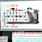
The illustration above shows a typical Type A OBD2 connector pinout, also known as the Data Link Connector (DLC). Key points about the OBD2 connector and its pins include:
- Location: Usually found near the steering wheel, though its exact location can be hidden.
- Pin 16: Provides battery power, often active even when the ignition is off.
- Pinout Variation: The function of specific pins depends on the communication protocol used by the vehicle.
- CAN Bus Pins: For CAN bus based OBD2 systems, pins 6 (CAN-High) and 14 (CAN-Low) are the designated OBD2 CAN pins and are essential for CAN communication.
OBD2 Connector Types: Type A vs. Type B and Pin Differences
You may encounter both Type A and Type B OBD2 connectors. Type A is standard in cars and light-duty vehicles, while Type B is more common in medium and heavy-duty vehicles.
While both types share a similar OBD2 pinout structure, there are key differences:
- Power Supply: Type A typically provides 12V power output, while Type B provides 24V.
- Baud Rate: Cars (Type A) often use a 500K baud rate for CAN, whereas heavy-duty vehicles (Type B) commonly use 250K (with increasing support for 500K in newer models).
- Physical Distinction: Type B connectors have an interrupted groove in the middle, allowing Type B OBD2 adapter cables to fit both Type A and Type B sockets, but Type A adapters will only fit Type A sockets.
OBD2 and CAN Bus: ISO 15765-4 and OBD2 CAN Pins
Since 2008, CAN bus (ISO 15765-4) has been the mandatory lower-layer protocol for OBD2 in US vehicles, making OBD2 CAN pins the primary interface for diagnostic communication.
ISO 15765-4, also known as Diagnostics over CAN (DoCAN), specifies how CAN is used for OBD2, focusing on the physical, data link, and network layers. Key specifications include:
- CAN Bit-rate: Must be either 250K or 500K.
- CAN IDs: Supports both 11-bit and 29-bit CAN identifiers.
- OBD2 Specific CAN IDs: Defined for OBD requests and responses.
- CAN Frame Data Length: Fixed at 8 bytes for diagnostic CAN frames.
- OBD2 Adapter Cable Length: Maximum length of 5 meters.
Understanding these specifications is crucial for correctly interfacing with OBD2 systems via OBD2 CAN pins.
OBD2 CAN Identifiers: 11-bit and 29-bit Addressing
OBD2 communication over CAN bus relies on request/response message pairs.
In most cars, 11-bit CAN IDs are used for OBD2 communication through OBD2 CAN pins. ‘Functional Addressing’ uses CAN ID 0x7DF, broadcasting requests to all OBD2-compatible ECUs. ‘Physical Addressing’ uses CAN IDs 0x7E0-0x7E7 for targeted requests to specific ECUs (less common).
ECUs respond using 11-bit IDs in the range 0x7E8-0x7EF. 0x7E8 (Engine Control Module – ECM) and 0x7E9 (Transmission Control Module – TCM) are the most frequent response IDs seen on OBD2 CAN pins.
Some vehicles, particularly vans and medium/heavy-duty vehicles, may use extended 29-bit CAN identifiers for OBD2 communication on their OBD2 CAN pins.
In 29-bit CAN, ‘Functional Addressing’ uses CAN ID 0x18DB33F1. Responses are typically in the range 0x18DAF100 to 0x18DAF1FF (common IDs include 18DAF110 and 18DAF11E). These response IDs are sometimes represented in J1939 PGN format, specifically PGN 0xDA00 (55808), reserved for ISO 15765-2 in the J1939-71 standard.
OBD2 vs. OEM-Specific CAN Protocols and OBD2 CAN Pins
It’s important to understand that OBD2 is an additional protocol running alongside your car’s primary, OEM-specific CAN protocols. Vehicle ECUs operate using proprietary CAN protocols defined by the manufacturer, which vary by brand, model, and year. These OEM protocols are typically inaccessible without reverse engineering.
Connecting a CAN bus data logger to your OBD2 connector may capture OEM-specific CAN data, often broadcast at high rates (1000-2000 frames/second). However, modern vehicles often employ a ‘gateway’ that restricts OBD2 connector access to OBD2 communication only, effectively blocking access to the underlying OEM CAN data through the OBD2 CAN pins.
Think of OBD2 as a parallel higher-layer protocol enabled for diagnostics, separate from the OEM’s core vehicle communication network. While both may be physically accessible through the OBD2 connector and its CAN pins, they serve different purposes and operate with distinct protocols.
Bit-rate and ID Validation for OBD2 CAN Pins
OBD2 over CAN can use two bit-rates (250K, 500K) and two CAN ID lengths (11-bit, 29-bit), resulting in four possible combinations for OBD2 CAN pins communication. Modern cars commonly use 500K and 11-bit IDs, but external tools should systematically validate these parameters.
ISO 15765-4 outlines a validation sequence to determine the correct combination. This method relies on the mandatory OBD2 PID 0x00 response and the detection of CAN error frames when using an incorrect bit-rate.
Newer ISO 15765-4 versions account for OBDonUDS alongside OBDonEDS. This article primarily focuses on OBDonEDS (OBD2, SAE OBD, EOBD, ISO OBD) as defined in ISO 15031-5/SAE J1979, versus WWH-OBD/OBDonUDS (OBD on Unified Diagnostic Service) based on ISO 14229, ISO 27145-3/SAE J1979-2.
To distinguish between OBDonEDS and OBDonUDS, test tools may send UDS requests with 11-bit/29-bit functional address IDs for service 0x22 and data identifier (DID) 0xF810 (protocol identification). Vehicles supporting OBDonUDS should respond to this DID via the OBD2 CAN pins.
OBDonEDS is prevalent in most non-EV cars today, while WWH-OBD is primarily used in EU trucks and buses.
Five Lower-Layer OBD2 Protocols Beyond CAN and OBD2 CAN Pins
While CAN (ISO 15765) is now dominant, older vehicles (pre-2008) may use other lower-layer protocols for OBD2. Understanding these alternative protocols and their corresponding OBD2 connector pin assignments can be helpful when working with older vehicles, even though CAN pins (6 and 14) are not relevant for these protocols.
- ISO 15765 (CAN bus): Mandatory in US cars since 2008, now widely used. Relies on OBD2 CAN pins 6 and 14.
- ISO14230-4 (KWP2000): Keyword Protocol 2000, common in 2003+ Asian cars. Uses different pins than OBD2 CAN pins.
- ISO 9141-2: Used in EU, Chrysler & Asian cars (2000-04). Utilizes different pins than OBD2 CAN pins.
- SAE J1850 (VPW): Variable Pulse Width Modulation, mostly in older GM cars. Pinout differs from OBD2 CAN pins.
- SAE J1850 (PWM): Pulse Width Modulation, mostly in older Ford cars. Pinout also differs from OBD2 CAN pins.
ISO-TP (ISO 15765-2) for OBD2 Message Transport via OBD2 CAN Pins
OBD2 data transmitted over OBD2 CAN pins utilizes the ISO-TP (ISO 15765-2) transport protocol. ISO-TP enables transmission of payloads exceeding the 8-byte CAN frame limit, necessary for OBD2 functions like retrieving VIN or DTCs. It handles segmentation, flow control, and reassembly of larger messages. For more details, refer to our UDS protocol introduction.
Often, OBD2 data fits within a single CAN frame. In these cases, ISO 15765-2 uses ‘Single Frame’ (SF) format. The first data byte (PCI field) indicates the payload length (excluding padding), leaving 7 bytes for OBD2 communication within the CAN frame transmitted via OBD2 CAN pins.
The OBD2 Diagnostic Message Structure and OBD2 CAN Pins
To understand OBD2 communication over OBD2 CAN pins, let’s examine the structure of a ‘Single Frame’ OBD2 CAN message. Simplified, it consists of a CAN identifier, data length (PCI field), and data payload. The payload is further structured into Mode, parameter ID (PID), and data bytes, all transmitted via the OBD2 CAN pins.
OBD2 Request/Response Example via OBD2 CAN Pins
Consider a request for ‘Vehicle Speed’ as an example of OBD2 communication using OBD2 CAN pins.
An external tool sends a request message via OBD2 CAN pins with CAN ID 0x7DF and 2 payload bytes: Mode 0x01 and PID 0x0D. The car responds via OBD2 CAN pins with CAN ID 0x7E8 and 3 payload bytes, including the vehicle speed value in the 4th byte, 0x32 (decimal 50).
Looking up OBD2 PID 0x0D, we find it represents Vehicle Speed, and the value 0x32 translates to 50 km/h. This communication happens over the OBD2 CAN pins (6 and 14).
The 10 OBD2 Services (Modes)
OBD2 defines 10 diagnostic services, or modes. Mode 0x01 provides real-time data, while others are used for DTCs, freeze frame data, and more. These modes are accessed through OBD2 CAN pins in CAN-based systems.
Vehicles are not required to support all 10 OBD2 modes and may implement OEM-specific modes beyond the standard set.
In OBD2 messages, the mode is the 2nd byte. In a request, the mode is directly included (e.g., 0x01). In a response, 0x40 is added to the mode value (e.g., 0x41 for a response to mode 0x01).
OBD2 Parameter IDs (PIDs) and OBD2 CAN Pins
Each OBD2 mode contains parameter IDs (PIDs). Mode 0x01, for example, includes approximately 200 standardized PIDs for real-time data like speed, RPM, and fuel level, all accessible via OBD2 CAN pins. However, vehicles typically support only a subset of these PIDs.
PID 0x00 in mode 0x01 is special: if an emissions-related ECU supports any OBD2 services, it must support mode 0x01 PID 0x00. Responding to PID 0x00, the ECU indicates support for PIDs 0x01-0x20. This makes PID 0x00 a fundamental OBD2 compatibility test when communicating through OBD2 CAN pins. Similarly, PIDs 0x20, 0x40, …, 0xC0 can be used to determine support for the remaining mode 0x01 PIDs, all queried and received via OBD2 CAN pins.
Tip: OBD2 PID Overview Tool
SAE J1979 and ISO 15031-5 appendices detail scaling information for standard OBD2 PIDs, allowing conversion of raw data received via OBD2 CAN pins into physical values.
Our OBD2 PID overview tool simplifies looking up mode 0x01 PIDs, constructing OBD2 request frames, and dynamically decoding OBD2 responses received through OBD2 CAN pins.
OBD2 PID Overview Tool
Logging and Decoding OBD2 Data via OBD2 CAN Pins
This section demonstrates logging OBD2 data using a CANedge CAN bus data logger connected to OBD2 CAN pins.
The CANedge allows configuration of custom CAN frames for transmission, enabling OBD2 data logging through the OBD2 connector and its CAN pins. Connect the CANedge to your vehicle using an OBD2-DB9 adapter cable to access OBD2 CAN pins.
Testing CAN frame transmission at 500K baud rate
Reviewing ‘Supported PIDs’ responses in asammdf software
Step #1: Test Bit-rate, IDs & Supported PIDs via OBD2 CAN Pins
As per ISO 15765-4, determine the bit-rate and CAN IDs used by your vehicle’s OBD2 system through OBD2 CAN pins. Use the CANedge for testing:
- Transmit a CAN frame at 500K baud and check for successful transmission (if unsuccessful, try 250K). This tests communication through OBD2 CAN pins at different speeds.
- Use the identified bit-rate for subsequent communication over OBD2 CAN pins.
- Send multiple ‘Supported PIDs’ requests via OBD2 CAN pins and review responses.
- Determine 11-bit or 29-bit CAN IDs based on response IDs received through OBD2 CAN pins.
- Identify supported PIDs based on response data obtained via OBD2 CAN pins.
Pre-configured settings are available for performing these tests efficiently.
Most post-2008 non-EV cars support 40-80 PIDs using 500K baud rate, 11-bit CAN IDs, and the OBD2/OBDonEDS protocol, all accessible via OBD2 CAN pins.
As shown in the asammdf GUI screenshot, multiple responses to a single OBD request are common when using the 0x7DF request ID, which polls all ECUs. Because all OBD2/OBDonEDS-compliant ECUs must support service 0x01 PID 0x00, numerous responses to this PID are often observed on OBD2 CAN pins. Fewer ECUs respond to subsequent ‘Supported PIDs’ requests. The ECM ECU (0x7E8) often supports all PIDs supported by other ECUs, suggesting reduced bus load by directing subsequent requests specifically to the ECM using ‘Physical Addressing’ CAN ID 0x7E0 via OBD2 CAN pins.
Step #2: Configure OBD2 PID Requests for OBD2 CAN Pins
After identifying supported PIDs, bit-rate, and CAN IDs, configure your transmit list with desired PIDs for logging data through OBD2 CAN pins.
Consider these factors:
- CAN IDs: Use ‘Physical Addressing’ request IDs (e.g., 0x7E0) to avoid multiple responses and streamline communication via OBD2 CAN pins.
- Spacing: Add 300-500 ms intervals between OBD2 requests to prevent ECU overload when communicating via OBD2 CAN pins.
- Battery Drain: Implement triggers to halt transmission when the vehicle is inactive, preventing ECU “wake-up” and battery drain when accessing OBD2 CAN pins.
- Filters: Filter to record only OBD2 responses if OEM-specific CAN data is also present on the OBD2 connector, focusing data logging on relevant OBD2 CAN pin communication.
With configuration complete, the device is ready to log raw OBD2 data transmitted over OBD2 CAN pins!
Example CANedge configuration for OBD2 PID requests via OBD2 CAN pins
asammdf software for DBC decoding and visualizing OBD2 data logged via OBD2 CAN pins
Step #3: DBC Decode Raw OBD2 Data from OBD2 CAN Pins
To analyze and visualize logged data from OBD2 CAN pins, decode the raw OBD2 data into physical values.
Decoding information is available in ISO 15031-5/SAE J1979 and online resources like Wikipedia. Our free OBD2 DBC file simplifies DBC decoding of raw OBD2 data obtained via OBD2 CAN pins in most CAN bus software tools.
Decoding OBD2 data from OBD2 CAN pins is more complex than standard CAN signals. Different OBD2 PIDs are transmitted using the same CAN ID (e.g., 0x7E8). Therefore, the CAN ID alone is insufficient to identify the signal within the payload received via OBD2 CAN pins.
Decoding requires using the CAN ID, OBD2 mode, and OBD2 PID to uniquely identify signals. This ‘extended multiplexing’ approach can be implemented in DBC files for accurate interpretation of data from OBD2 CAN pins.
CANedge: Your OBD2 Data Logger for OBD2 CAN Pins
The CANedge enables easy recording of OBD2 data to an 8-32 GB SD card via OBD2 CAN pins. Connect it to a car or truck to start logging and decode data using free software/APIs and our OBD2 DBC file.
OBD2 logger introduction
CANedge product page
OBD2 Multi-Frame Examples and ISO-TP over OBD2 CAN Pins
OBD2 communication, including multi-frame messages, utilizes ISO-TP (ISO 15765-2) over OBD2 CAN pins. While previous examples focused on single-frame communication, multi-frame communication is necessary for larger data sets.
Multi-frame OBD2 communication through OBD2 CAN pins requires flow control frames. A static flow control frame transmitted ~50 ms after the initial request frame, as demonstrated in the CANedge configuration example, handles flow control.
Analyzing multi-frame OBD2 responses from OBD2 CAN pins necessitates CAN software/API tools with ISO-TP support, such as CANedge MF4 decoders.
Example 1: OBD2 Vehicle Identification Number (VIN) Retrieval via OBD2 CAN Pins
Retrieving the Vehicle Identification Number (VIN) using OBD2 requests over OBD2 CAN pins (mode 0x09 and PID 0x02) is relevant for telematics and diagnostics.
The tester tool sends a Single Frame request containing the PCI field (0x02), request service identifier (0x09), and PID (0x02) via OBD2 CAN pins.
The vehicle responds via OBD2 CAN pins with a First Frame containing PCI, length (0x014 = 20 bytes), mode (0x49), and PID (0x02). Following the PID is the Number Of Data Items (NODI) byte (0x01, indicating one item). The subsequent 17 bytes represent the VIN, convertible from HEX to ASCII.
Example 2: OBD2 Multi-PID Request (6x) via OBD2 CAN Pins
External tools can request up to six mode 0x01 OBD2 PIDs in a single request frame transmitted via OBD2 CAN pins. The ECU responds with data for supported PIDs (omitting unsupported PIDs), potentially using multi-frame responses as per ISO-TP, all communicated via OBD2 CAN pins.
This method increases data collection efficiency but complicates signal encoding, making generic OBD2 DBC files less effective. We advise against this method for general use.
Multi-frame responses resemble the VIN example, but the payload includes requested PIDs and their corresponding data. PID order in the response often mirrors the request order, which is common but not strictly required by ISO 15031-5.
Decoding such responses via generic DBC files is challenging. This approach uses extended multiplexing with multiple instances within the payload. DBC files would need to account for PID-specific payload positions, making generalization across vehicles difficult. Handling multiple multi-PID requests further complicates DBC-based decoding.
Custom scripts combined with recording request messages can help interpret responses by linking them to requests, but scaling such approaches is complex.
Example 3: OBD2 Diagnostic Trouble Codes (DTCs) via OBD2 CAN Pins
OBD2 mode 0x03 (‘Show stored Diagnostic Trouble Codes’) requests emissions-related DTCs via OBD2 CAN pins. The request omits a PID. Responding ECUs indicate the number of stored DTCs (possibly zero) and provide 2-byte DTC values, requiring multi-frame responses for more than two DTCs, all transmitted via OBD2 CAN pins.
The 2-byte DTC value is categorized and includes a 4-digit hexadecimal code, as per ISO 15031-5/ISO 15031-6. DTC values can be looked up using OBD2 DTC lookup tools like repairpal.com.
The example below shows a request to an ECU with six stored DTCs, communicated via OBD2 CAN pins.
OBD2 Data Logging Use Cases and OBD2 CAN Pins
OBD2 data accessed via OBD2 CAN pins is valuable in numerous applications for cars and light trucks:
Car Data Logging
OBD2 data logging helps reduce fuel costs, improve driving habits, test prototype components, and optimize insurance models. Data is accessed via OBD2 CAN pins.
OBD2 logger product details
Real-Time Car Diagnostics
OBD2 interfaces enable real-time streaming of human-readable OBD2 data, facilitating vehicle issue diagnosis using data from OBD2 CAN pins.
OBD2 streaming interface information
Predictive Maintenance
IoT OBD2 loggers monitor cars and light trucks via the cloud, predicting and preventing breakdowns using data accessed through OBD2 CAN pins.
Predictive maintenance solutions using CAN bus and OBD2
Vehicle Black Box Logger
OBD2 loggers serve as ‘black boxes’ for vehicles and equipment, providing data for dispute resolution and diagnostics via OBD2 CAN pins.
CAN bus black box logger details
Have an OBD2 data logging use case? Contact us for expert consultation!
Contact Us
Explore our guides section for more introductions, or download the ‘Ultimate Guide’ PDF.
Need to log or stream OBD2 data via OBD2 CAN pins?
Get your OBD2 data logger today!
Buy Now Contact Us
Recommended for You
OBD2 DATA LOGGER: EASILY LOG & CONVERT OBD2 DATA
CANEDGE2 – PRO CAN IoT LOGGER
CAN BUS INTERFACE: STREAMING OBD2 DATA WITH SAVVYCAN