As a car owner or automotive enthusiast, you’ve likely heard of OBD2. But do you truly understand what it is and, more importantly, how the Obd2 Connector plays a pivotal role in modern vehicle diagnostics and data access?
This comprehensive guide, brought to you by the experts at obd-de.com, dives deep into the world of On-Board Diagnostics (OBD2), with a laser focus on the OBD2 connector. We’ll break down the complexities into simple, practical terms, making this essential knowledge accessible to everyone from DIY mechanics to seasoned professionals.
Think of the OBD2 connector as the gateway to your vehicle’s inner workings. It’s through this port that mechanics diagnose issues, emissions are tested, and performance data is extracted. But it’s more than just a port; it’s a standardized interface that has revolutionized the automotive repair and data analysis landscape.
In this article, you’ll learn:
- What OBD2 is and why it matters.
- The history and evolution of OBD2, emphasizing the standardization of the OBD2 connector.
- The crucial role of the OBD2 connector in accessing vehicle data.
- Different types of OBD2 connectors and their pinouts.
- How the OBD2 connector interfaces with CAN bus and other protocols.
- Practical tips for using the OBD2 connector for diagnostics and data logging.
Whether you’re troubleshooting a check engine light, monitoring your car’s performance, or developing automotive applications, understanding the OBD2 connector is fundamental. Let’s embark on this journey to unlock the secrets hidden within this vital automotive component.
Understanding OBD2 and the Malfunction Indicator Light (MIL), often accessed through the OBD2 connector.
What Exactly is OBD2?
OBD2, or On-Board Diagnostics II, is your car’s built-in self-diagnostic system. It’s a standardized protocol that allows you to retrieve diagnostic trouble codes (DTCs) and real-time data from your vehicle. The key to accessing this information? The OBD2 connector.
You’ve probably encountered OBD2 symptoms without realizing it. That check engine light illuminating on your dashboard? That’s OBD2 at work, signaling that your car has detected an issue. When you take your car to a mechanic, the first thing they’ll likely do is plug an OBD2 scanner into the OBD2 connector, typically located near the steering wheel.
This OBD2 connector serves as the physical interface for communication. The scanner sends ‘OBD2 requests’ through the connector to the car’s computer. The car, in turn, responds with ‘OBD2 responses’, delivering data like speed, engine temperature, fuel levels, and those all-important Diagnostic Trouble Codes (DTCs). This streamlined communication, facilitated by the OBD2 connector, makes troubleshooting automotive problems significantly faster and more efficient.
Does Your Car Have an OBD2 Connector?
The answer is almost certainly yes, especially if you own a car manufactured in recent decades.
Nearly all modern non-electric cars are equipped with OBD2 and predominantly operate on the CAN bus protocol. However, it’s worth noting that the presence of a 16-pin OBD2 connector doesn’t automatically guarantee OBD2 compliance, particularly in older vehicles. Some older cars may feature the physical connector but not fully support the OBD2 protocol.
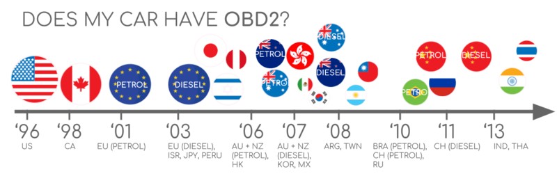
To ascertain OBD2 compliance, consider the vehicle’s origin and year of purchase:
A helpful chart to determine OBD2 compliance based on vehicle origin and purchase year.
A Brief History of OBD2 and the OBD2 Connector
The genesis of OBD2 can be traced back to California, where the California Air Resources Board (CARB) mandated OBD systems in all new cars from 1991 onwards for emission control. This marked the initial push for standardized vehicle diagnostics.
The OBD2 standard, including the now-ubiquitous OBD2 connector, was further refined and recommended by the Society of Automotive Engineers (SAE). This led to the standardization of DTCs and, crucially, the OBD connector itself across different vehicle manufacturers under the SAE J1962 standard. This standardization of the OBD2 connector was a game-changer, enabling universal diagnostic tools to interface with a wide range of vehicles.
The rollout of the OBD2 standard was gradual but impactful:
- 1996: OBD2 became mandatory in the USA for cars and light trucks. This was a significant step, making the OBD2 connector and protocol a standard feature in the US automotive market.
- 2001: The European Union mandated OBD2 for gasoline cars, expanding the reach of the OBD2 connector and diagnostics.
- 2003: The EU extended the mandate to include diesel cars (EOBD), ensuring broader adoption of OBD2 across Europe.
- 2005: OBD2 compliance was required in the US for medium-duty vehicles, further solidifying the OBD2 connector’s role in vehicle diagnostics.
- 2008: US vehicles were required to use ISO 15765-4 (CAN) as the OBD2 communication basis, standardizing the communication protocols used through the OBD2 connector.
- 2010: OBD2 became mandatory in US heavy-duty vehicles, completing the widespread adoption of OBD2 and its connector in the US automotive industry.
The historical progression of OBD2, driven by emission control and standardization.
A timeline visualizing the key milestones in OBD2 history.
Looking ahead to OBD3 and the future of vehicle diagnostics and remote data access.
The Future of OBD2 and the OBD2 Connector
While OBD2, and consequently the OBD2 connector, is firmly entrenched in automotive diagnostics, its future is evolving.
Originally designed for emission control and testing, legislated OBD2 has faced new challenges and adaptations. Electric vehicles (EVs), for instance, aren’t obligated to support OBD2 in its traditional form. Interestingly, most modern EVs don’t support standard OBD2 requests, often opting for OEM-specific UDS communication. This shift can make accessing data from EVs challenging, except in cases where reverse engineering efforts have yielded decoding methods, as seen in case studies for Tesla, Hyundai/Kia, Nissan, and VW/Skoda EVs.
In response to the limitations of traditional OBD2 in terms of data richness and lower-layer protocols, modern alternatives like WWH-OBD (World Wide Harmonized OBD) and OBDonUDS (OBD on UDS) have emerged. These protocols aim to enhance OBD communication by utilizing the UDS protocol as a foundation, still relying on the OBD2 connector as the physical interface.
The rise of connected cars is also shaping the future of OBD2. Manual emission checks are becoming increasingly cumbersome. OBD3 proposes a solution by integrating telematics into all vehicles. Imagine OBD3 adding a small radio transponder to cars, enabling the vehicle identification number (VIN) and DTCs to be wirelessly transmitted to a central server for automated checks. This concept, while streamlining processes, raises privacy and surveillance concerns.
Furthermore, the automotive industry is grappling with the use of OBD2 for third-party data access. Originally intended for repair shop servicing, OBD2 is now widely used by third parties for real-time data generation via OBD2 dongles and CAN loggers. However, concerns about data security and manufacturer control are leading to discussions about potentially limiting OBD2 functionality during driving, with data collection centralized via OEM servers. This could significantly impact the market for third-party OBD2 connector-based services.
The evolving landscape of OBD2 in the era of electric vehicles and data access control.
Unlock the Full Picture with Our ‘Ultimate CAN Guide’
Eager to become a CAN bus expert and deepen your understanding of OBD2?
Our comprehensive 160+ page PDF, ‘Ultimate CAN Guide’, offers 12 simple introductions to navigate the intricacies of CAN bus technology.
Download now
OBD2 Standards and the OBD2 Connector
Understanding OBD2 standards is crucial for anyone working with vehicle diagnostics. On-Board Diagnostics (OBD2) itself is a higher-layer protocol, much like a language, while CAN bus is the communication method, akin to a phone line. OBD2 operates alongside other CAN-based higher-layer protocols like J1939, CANopen, and NMEA 2000.
OBD2 standards meticulously define various aspects, including the OBD2 connector, lower-layer protocols, and OBD2 parameter IDs (PIDs). These standards can be categorized within the 7-layer OSI model. Notably, both SAE and ISO standards contribute to different layers, reflecting the standardization efforts in the USA (SAE) and EU (ISO). Many of these standards are technically very similar, for instance, SAE J1979 and ISO 15031-5, or SAE J1962 and ISO 15031-3.
The relationship between OBD2 and CAN bus within the OSI 7-layer model.
The pinout diagram for a Type A OBD2 connector, as specified in SAE J1962.
Delving into the OBD2 Connector [SAE J1962 / ISO 15031-3]
The 16-pin OBD2 connector is the standardized interface that grants easy access to your car’s data. It’s meticulously defined by the SAE J1962 standard (also known as ISO 15031-3).
The illustration above showcases a Type A OBD2 pin connector, sometimes referred to as the Data Link Connector (DLC).
Key features of the OBD2 connector include:
- Location: Typically found near the steering wheel, though it may be subtly hidden behind a panel.
- Pin 16: Provides battery power, often even when the ignition is off, ensuring constant power for diagnostic tools.
- Pinout Variability: The specific pinout arrangement is protocol-dependent, accommodating different communication standards.
- CAN Bus Integration: In most modern vehicles, CAN bus is the dominant lower-layer protocol, meaning pins 6 (CAN-H) and 14 (CAN-L) are usually connected for CAN communication through the OBD2 connector.
OBD2 Connector Types: A vs. B
In practical applications, you might encounter both Type A and Type B OBD2 connectors. Type A is commonly found in cars and light-duty vehicles, while Type B is prevalent in medium and heavy-duty vehicles.
While both types share a similar pinout structure, they differ primarily in power supply outputs: Type A typically provides 12V, whereas Type B delivers 24V. Baud rates can also vary, with cars often using 500K and heavy-duty vehicles commonly employing 250K (though 500K support is increasing).
Visually distinguishing between the two OBD2 connector types is straightforward: Type B connectors feature an interrupted groove in the center. This design ensures that a Type B OBD2 adapter cable is compatible with both Type A and Type B sockets, while a Type A adapter will only fit into a Type A socket.
Visual comparison of OBD2 Connector Type A and Type B, highlighting key differences.
Illustrating the relationship between OBD2, CAN bus, and the ISO 15765 standard.
OBD2 and CAN Bus: Communication via the OBD2 Connector [ISO 15765-4]
Since 2008, CAN bus has been the mandatory lower-layer protocol for OBD2 in all US-sold vehicles, as mandated by ISO 15765. This means that communication through the OBD2 connector in modern vehicles predominantly relies on CAN bus.
ISO 15765-4, also known as Diagnostics over CAN (DoCAN), imposes specific constraints on the CAN standard (ISO 11898) for OBD2 applications. It standardizes the CAN interface for diagnostic equipment, focusing on the physical, data link, and network layers. Key specifications include:
- Bit-rate: CAN bus bit-rate must be either 250K or 500K for OBD2 communication via the OBD2 connector.
- CAN IDs: Supports both 11-bit and 29-bit CAN identifiers for flexibility.
- Specific CAN IDs: Defines reserved CAN IDs specifically for OBD requests and responses transmitted through the OBD2 connector.
- Data Length: Diagnostic CAN frame data length is fixed at 8 bytes for streamlined communication.
- Cable Length: The OBD2 adapter cable, connecting to the OBD2 connector, must not exceed 5 meters to ensure signal integrity.
OBD2 CAN Identifiers (11-bit, 29-bit)
OBD2 communication invariably involves request and response message exchanges through the OBD2 connector and CAN bus.
In most cars, 11-bit CAN IDs are used for OBD2 communication. The ‘Functional Addressing’ ID is 0x7DF, which queries all OBD2-compatible ECUs for data related to the requested parameter. CAN IDs ranging from 0x7E0 to 0x7E7 are used for ‘Physical Addressing’ requests directed to specific ECUs, though this is less common.
ECUs respond with 11-bit IDs in the range of 0x7E8 to 0x7EF. The most frequent response ID is 0x7E8 (Engine Control Module, ECM), followed by 0x7E9 (Transmission Control Module, TCM).
Some vehicles, particularly vans and medium to heavy-duty vehicles, utilize extended 29-bit CAN identifiers for OBD2 communication instead of 11-bit IDs.
In 29-bit CAN, the ‘Functional Addressing’ CAN ID is 0x18DB33F1. Responses are typically observed with CAN IDs ranging from 0x18DAF100 to 0x18DAF1FF, often 18DAF110 and 18DAF11E. The response ID is sometimes represented in the J1939 PGN format, specifically PGN 0xDA00 (55808), which is designated as ‘Reserved for ISO 15765-2’ in the J1939-71 standard.
Illustrating the request-response message flow in OBD2 communication.
Contrasting OBD2 communication with OEM-specific CAN bus protocols.
OBD2 vs. Proprietary CAN Protocols
It’s essential to understand that your car’s electronic control units (ECUs) operate using OEM-specific proprietary CAN protocols, independently of OBD2. Each vehicle manufacturer implements unique CAN protocols tailored to their specific vehicle brands, models, and years. This OEM-specific data is typically inaccessible to third parties without reverse engineering efforts.
Connecting a CAN bus data logger to your car’s OBD2 connector might capture OEM-specific CAN data, often broadcast at high rates (1000-2000 frames/second). However, many newer vehicles incorporate a ‘gateway’ that restricts access to this OEM CAN data through the OBD2 connector, exclusively enabling OBD2 communication.
In essence, think of OBD2 as an ‘additional’ higher-layer protocol functioning in parallel with the OEM-specific protocol. The OBD2 connector serves as a shared physical interface for both, but access and data interpretation differ significantly.
Bit-rate and ID Validation
OBD2 communication can occur at two bit-rates (250K, 500K) and with two CAN ID lengths (11-bit, 29-bit), resulting in four potential combinations. Modern cars commonly use 500K and 11-bit IDs. Diagnostic tools need to systematically validate these parameters.
ISO 15765-4 provides guidelines for an initialization sequence to determine the correct combination. This method relies on the fact that OBD2-compliant vehicles must respond to a specific mandatory OBD2 request (detailed in the OBD2 PID section) and that incorrect bit-rate transmissions will generate CAN error frames.
Newer ISO 15765-4 versions also account for vehicles supporting OBD communication via OBDonUDS rather than OBDonEDS. This article primarily focuses on OBD2/OBDonEDS (OBD on emission diagnostic service as per ISO 15031-5/SAE J1979) as opposed to WWH-OBD/OBDonUDS (OBD on Unified Diagnostic Service as per ISO 14229, ISO 27145-3/SAE J1979-2).
To differentiate between OBDonEDS and OBDonUDS protocols, diagnostic tools may send additional UDS requests with 11-bit/29-bit functional address IDs for service 0x22 and data identifier (DID) 0xF810 (protocol identification). OBDonUDS-compliant vehicles should have ECUs that respond to this DID.
In practice, OBDonEDS (also known as OBD2, SAE OBD, EOBD, or ISO OBD) is prevalent in most non-EV cars today, while WWH-OBD is mainly used in EU trucks and buses.
A flowchart outlining the process for OBD2 bit-rate and CAN ID validation.
An overview of the five lower-layer OBD2 protocols.
Five Lower-Layer OBD2 Protocols
While CAN (ISO 15765) is now the dominant lower-layer protocol for OBD2, especially in vehicles accessed via the OBD2 connector, older vehicles (pre-2008) may utilize other protocols. Understanding these alternatives is useful when working with legacy systems. The pinouts of the OBD2 connector can sometimes indicate the protocol in use.
- ISO 15765 (CAN bus): Mandatory in US cars since 2008 and widely adopted today. Communication happens through the OBD2 connector.
- ISO14230-4 (KWP2000): Keyword Protocol 2000, common in 2003+ cars, particularly in Asia.
- ISO 9141-2: Used in EU, Chrysler, and Asian cars around 2000-04.
- SAE J1850 (VPW): Predominantly used in older GM vehicles.
- SAE J1850 (PWM): Mostly found in older Ford vehicles.
Transporting OBD2 Messages via ISO-TP [ISO 15765-2]
All OBD2 data exchanged through the OBD2 connector over CAN bus utilizes the ISO-TP (ISO 15765-2) transport protocol. This protocol enables the transmission of payloads exceeding the 8-byte CAN frame limit. This is crucial for OBD2 functionalities like retrieving the Vehicle Identification Number (VIN) or Diagnostic Trouble Codes (DTCs). ISO 15765-2 handles segmentation, flow control, and reassembly of these larger messages.
However, much of the time, OBD2 data fits within a single CAN frame. In such cases, ISO 15765-2 specifies the use of ‘Single Frame’ (SF) formatting. Here, the first data byte (PCI field) indicates the payload length (excluding padding), leaving 7 bytes for OBD2-related communication.
Illustrating the different frame types defined in ISO 15765-2 for OBD2 communication.
Decoding the OBD2 Diagnostic Message [SAE J1979, ISO 15031-5]
To effectively work with OBD2 over CAN, especially when interacting via the OBD2 connector, understanding the structure of a raw ‘Single Frame’ OBD2 CAN message is vital. In simple terms, an OBD2 message consists of an identifier, data length (PCI field), and data payload. The data payload is further structured into Mode, parameter ID (PID), and data bytes.
Breaking down the structure of an OBD2 message frame.
Example: OBD2 Request/Response via the OBD2 Connector
Let’s examine a practical example of requesting and receiving the ‘Vehicle Speed’ parameter via the OBD2 connector.
An external tool sends a request message to the car through the OBD2 connector. This message has a CAN ID of 0x7DF and a 2-byte payload: Mode 0x01 and PID 0x0D. The car responds via the OBD2 connector with a CAN ID of 0x7E8 and a 3-byte payload. The vehicle speed value is contained in the 4th byte, 0x32 (which is 50 in decimal).
By consulting the OBD2 PID decoding rules for PID 0x0D, we can determine that the physical value corresponds to 50 km/h. This simple request-response sequence highlights the fundamental communication method through the OBD2 connector.
Example of an OBD2 request and response sequence for vehicle speed.
Detailed look at OBD2 PID 0x0D, representing vehicle speed.
Overview of the 10 standardized OBD2 service modes.
The 10 OBD2 Services (Modes)
There are 10 defined OBD2 diagnostic services, often referred to as modes. Mode 0x01 is used to retrieve current real-time data, while other modes are employed to access and clear diagnostic trouble codes (DTCs) or retrieve freeze frame data. These services are all accessed via the OBD2 connector.
It’s important to note that vehicles aren’t required to support all 10 OBD2 modes. They may also implement OEM-specific modes beyond these standardized ones.
In OBD2 messages, the mode is typically located in the second byte. In a request message, the mode is included directly (e.g., 0x01). In a response message, 0x40 is added to the requested mode value (e.g., resulting in 0x41 for a response to mode 0x01).
OBD2 Parameter IDs (PIDs)
Within each OBD2 mode, there are Parameter IDs (PIDs). Mode 0x01, for example, contains approximately 200 standardized PIDs providing real-time data on parameters like speed, RPM, and fuel level. However, vehicles are not obligated to support all PIDs within a mode. In practice, most vehicles only support a subset of the available PIDs. These PIDs are accessed through requests sent via the OBD2 connector.
One PID holds a special significance: PID 0x00 in mode 0x01. If an emissions-related ECU supports any OBD2 services, it must support mode 0x01 PID 0x00. Responding to this PID, the vehicle ECU indicates whether it supports PIDs 0x01-0x20. This makes PID 0x00 a fundamental ‘OBD2 compatibility test’ when establishing communication through the OBD2 connector. Similarly, PIDs 0x20, 0x40, and so on, up to 0xC0, can be used to determine support for the remaining mode 0x01 PIDs.
Reiterating the request-response paradigm with PIDs in OBD2.
A preview of an OBD2 PID overview tool, useful for exploring service 01 PIDs.
Tip: OBD2 PID Overview Tool
The appendices of SAE J1979 and ISO 15031-5 contain scaling information for standard OBD2 PIDs, enabling you to convert raw data into physical values.
For quick PID lookups, especially for mode 0x01, our OBD2 PID overview tool is invaluable. It assists in constructing OBD2 request frames and dynamically decoding OBD2 responses, streamlining your interaction with the OBD2 connector and vehicle data.
OBD2 PID overview tool
Practical Guide: Logging and Decoding OBD2 Data via the OBD2 Connector
Let’s walk through a practical example of logging OBD2 data using the CANedge CAN bus data logger. The CANedge allows custom CAN frame transmission, making it ideal for OBD2 logging through the OBD2 connector.
Connecting the CANedge to your vehicle is simplified using our OBD2-DB9 adapter cable, which interfaces directly with the OBD2 connector.
Illustrating an OBD2 data logger requesting PIDs via the OBD2 connector.
Reviewing responses to ‘Supported PIDs’ requests in asammdf.
Step #1: Bit-rate, ID, and Supported PID Testing
As per ISO 15765-4, determining the correct bit-rate and IDs for your vehicle is crucial. Here’s how to test using CANedge:
- Bit-rate Test: Transmit a CAN frame at 500K. If successful, proceed. If not, try 250K. This ensures proper communication through the OBD2 connector.
- Bit-rate Confirmation: Use the identified bit-rate for all subsequent communication.
- Supported PIDs Request: Send multiple ‘Supported PIDs’ requests via the OBD2 connector and review the responses.
- ID Type Determination: Response IDs will indicate whether the vehicle uses 11-bit or 29-bit CAN IDs for OBD2 communication.
- PID Support Discovery: Response data reveals the PIDs supported by the vehicle.
We offer plug-and-play configurations to simplify these tests. Most 2008+ non-EV cars support 40-80 PIDs using 500K bit-rate, 11-bit CAN IDs, and the OBD2/OBDonEDS protocol when accessed via the OBD2 connector.
Analyzing responses in tools like asammdf reveals that a single OBD request can elicit multiple responses, especially when using the 0x7DF request ID, which polls all ECUs. Since all OBD2/OBDonEDS-compliant ECUs must support service 0x01 PID 0x00, numerous responses to this PID are common. As you request subsequent ‘Supported PIDs’, fewer ECUs might respond. Notice that the ECM ECU (0x7E8) often supports all PIDs supported by other ECUs in the example, suggesting that reducing bus load by directly querying the ECM using ‘Physical Addressing’ CAN ID 0x7E0 for subsequent communication may be beneficial.
Step #2: Configuring OBD2 PID Requests
Once you’ve identified supported PIDs, bit-rate, and CAN IDs, configure your transmit list with the PIDs you want to log. Consider these points:
- CAN IDs: Switch to ‘Physical Addressing’ request IDs (e.g., 0x7E0) to minimize redundant responses.
- Request Spacing: Introduce 300-500 ms intervals between OBD2 requests to prevent ECU overload.
- Battery Conservation: Use triggers to halt transmission when the vehicle is inactive, preventing unnecessary ECU ‘wake-up’ and battery drain through the OBD2 connector.
- Data Filtering: Implement filters to record only OBD2 responses, especially if OEM-specific CAN data is also present.
With these configurations, your CANedge is ready to log raw OBD2 data from the OBD2 connector!
Example CANedge OBD2 PID request list configuration.
Visualizing DBC-decoded OBD2 data plots in asammdf.
Step #3: DBC Decoding of Raw OBD2 Data
To analyze and visualize logged OBD2 data, you need to decode the raw data into ‘physical values’. Decoding information is found in ISO 15031-5/SAE J1979 and online resources like Wikipedia. We provide a free OBD2 DBC file to simplify DBC decoding in most CAN bus software tools.
Decoding OBD2 data is slightly more complex than standard CAN signals because different OBD2 PIDs share the same CAN ID (e.g., 0x7E8). The CAN ID alone isn’t enough to identify signals within the payload.
The solution is to use the CAN ID, OBD2 mode, and OBD2 PID together for signal identification. This is a form of ‘extended multiplexing’, which can be implemented in DBC files.
CANedge: Your OBD2 Data Logger
The CANedge is designed for easy OBD2 data recording to SD cards (8-32 GB). Connect it to your car or truck via the OBD2 connector to start logging. Use our free software and APIs, along with our OBD2 DBC file, for data decoding and analysis.
OBD2 logger intro CANedge
OBD2 Multi-Frame Examples [ISO-TP]
While single-frame examples are common in OBD2, multi-frame communication, handled by ISO-TP, is essential for larger data transfers via the OBD2 connector.
Multi-frame OBD2 communication necessitates flow control frames. A common approach is to transmit a static flow control frame approximately 50 ms after the initial request frame, as demonstrated in the CANedge configuration example.
Analyzing multi-frame OBD2 responses requires CAN software and API tools that support ISO-TP, such as CANedge MF4 decoders.
Example of a multi-frame request for the Vehicle Identification Number (VIN) via the OBD2 connector.
Example 1: OBD2 Vehicle Identification Number (VIN) Retrieval
Retrieving the VIN, often crucial for telematics and diagnostics, uses mode 0x09 and PID 0x02.
The tester tool sends a Single Frame request with PCI field (0x02), request service identifier (0x09), and PID (0x02) through the OBD2 connector.
The vehicle responds with a First Frame containing PCI, length (0x014 = 20 bytes), mode (0x49), and PID (0x02). Following the PID is the Number Of Data Items (NODI), in this case 1. The subsequent 17 bytes represent the VIN, which can be converted from HEX to ASCII.
Example 2: OBD2 Multi-PID Request (6x)
OBD2 allows requesting up to 6 mode 0x01 PIDs in a single request frame via the OBD2 connector. The ECU responds with data for supported PIDs, potentially using multi-frame responses.
While efficient, this method complicates signal encoding and generic DBC file usage. We generally advise against this approach in practice. The example trace below illustrates a multi-PID request scenario.
The multi-frame response structure is similar to the VIN example, but includes requested PIDs and their corresponding data. The PIDs are often ordered as requested, though not strictly mandated by ISO 15031-5.
Decoding such responses with generic DBC files is challenging due to the complex multiplexing and PID-specific payload positions. Custom scripts and recording request messages alongside responses can help, but scaling such approaches is difficult.
Example 3: OBD2 Diagnostic Trouble Codes (DTCs) Retrieval
OBD2 mode 0x03, ‘Show stored Diagnostic Trouble Codes’, is used to request emissions-related DTCs. No PID is included in the request. The ECU responds with the number of stored DTCs (possibly zero) and the DTCs themselves, each occupying 2 bytes. Multi-frame responses are necessary if more than 2 DTCs are stored. Accessing DTCs is a primary function of the OBD2 connector.
The 2-byte DTC value is structured according to ISO 15031-5/ISO 15031-6. The first 2 bits define the ‘category’, and the remaining 14 bits form a 4-digit hexadecimal code. Decoded DTC values can be looked up using OBD2 DTC lookup tools like repairpal.com.
The example below shows a request to an ECU with 6 stored DTCs.
Decoding and interpreting OBD2 Diagnostic Trouble Codes (DTCs).
Real-World OBD2 Data Logging Use Cases via the OBD2 Connector
OBD2 data, readily accessible through the OBD2 connector, has diverse applications across various industries:
Car Data Logging
OBD2 data logging in cars can optimize fuel efficiency, improve driving habits, facilitate prototype testing, and inform insurance assessments. All starting with a connection to the OBD2 connector.
obd2 logger
Real-time Car Diagnostics
OBD2 interfaces, connected via the OBD2 connector, enable real-time streaming of human-readable OBD2 data, crucial for diagnosing vehicle issues on the fly.
obd2 streaming
Predictive Maintenance
IoT-enabled OBD2 loggers, utilizing the OBD2 connector, allow remote monitoring of cars and light trucks in the cloud for predictive maintenance, preventing breakdowns before they occur.
predictive maintenance
Vehicle Black Box Logger
An OBD2 logger, plugged into the OBD2 connector, can function as a ‘black box’ for vehicles, providing critical data for dispute resolution, accident reconstruction, and in-depth diagnostics.
can bus blackbox
Do you have a specific OBD2 data logging use case in mind? Reach out to us for expert consultation!
Contact us
Explore our guides section for more in-depth intros or download our ‘Ultimate Guide’ PDF for a comprehensive resource.
Ready to start logging or streaming OBD2 data?
Get your OBD2 data logger today!
Buy now Contact us
Recommended Resources
OBD2 DATA LOGGER: EASILY LOG & CONVERT OBD2 DATA
CANEDGE2 – PRO CAN IoT LOGGER
[
