Demystifying the Obd2 Connector Pin Diagram for car diagnostics and data access.
Are you looking to understand your car’s On-Board Diagnostics system? The OBD2 protocol is crucial for accessing vehicle data, diagnosing issues, and even enhancing your car’s performance. At the heart of this system is the OBD2 connector. This guide provides a detailed look into the OBD2 connector pin diagram, explaining its pinouts, associated protocols, and how it serves as the gateway to your vehicle’s inner workings.
Whether you’re a car enthusiast, a seasoned mechanic, or an engineer working with automotive systems, understanding the OBD2 connector pin diagram is essential. Let’s dive in and explore the world of OBD2, starting with its most tangible component: the connector.
Understanding the OBD2 Connector
The OBD2 connector, formally known as the SAE J1962 Diagnostic Connector, is a standardized 16-pin interface found in most modern vehicles. It’s your direct access point to your car’s diagnostic information and real-time data. If you’ve ever seen the check engine light illuminate on your dashboard, or if you’ve visited a mechanic for a diagnostic check, the OBD2 connector is the key component that makes this communication possible.
What is the OBD2 Connector? (DLC, J1962)
The OBD2 connector is often referred to as the Data Link Connector (DLC). Its standardization is defined by SAE J1962 and ISO 15031-3 standards, ensuring compatibility across different vehicle makes and models. This standardization is a significant advantage, allowing universal OBD2 scanners and tools to interface with a wide range of vehicles.
Understanding OBD2: On-Board Diagnostics explained with a malfunction indicator light and scan tool.
Why is the OBD2 Connector Standardized?
The standardization of the OBD2 connector was driven by regulatory requirements, primarily for emissions control. The California Air Resources Board (CARB) initially mandated OBD in 1991 for emission monitoring. Later, OBD2 became mandatory in the USA in 1996 and in the EU in the early 2000s. This standardization ensures that all compliant vehicles provide access to emissions-related diagnostic data through a common interface – the 16-pin OBD2 connector. Beyond emissions, this standardized connector has become a valuable tool for broader vehicle diagnostics and data acquisition.
Location of the OBD2 Connector in Your Car
The OBD2 connector is typically located within easy reach of the driver, often under the dashboard on the driver’s side. However, the exact location can vary depending on the vehicle manufacturer and model. It’s usually found within a foot or two of the steering wheel. Sometimes it may be slightly hidden under a panel, but it is designed to be accessible without special tools. If you’re unsure, consult your vehicle’s owner’s manual for the precise location of the OBD2 connector.
OBD2 Connector Pin Diagram Explained
Now, let’s delve into the heart of the matter: the OBD2 connector pin diagram. Understanding the function of each pin is crucial for anyone working with OBD2 tools, cables, or custom applications. The 16 pins in the OBD2 connector are assigned specific functions, primarily related to power, ground, communication protocols, and manufacturer-specific use.
Pinout of the Type A OBD2 Connector
The Type A OBD2 connector is the most common type found in passenger cars and light-duty vehicles. Here’s a detailed breakdown of the pinout:
| Pin Number | Pin Name | Function |
|---|---|---|
| 1 | Manufacturer Discretionary | Manufacturer Specific – Varies by manufacturer |
| 2 | SAE J1850 Bus+ | SAE J1850 VPW or PWM bus positive line (older Ford/GM vehicles) |
| 3 | Manufacturer Discretionary | Manufacturer Specific – Varies by manufacturer |
| 4 | Chassis Ground | Ground for vehicle chassis |
| 5 | Signal Ground | Signal ground for control modules |
| 6 | CAN High (CAN-H) | CAN bus High line (ISO 15765-4 and others) |
| 7 | ISO 9141-2 K-Line | K-line for ISO 9141-2 and ISO 14230-4 (KWP2000) protocols (older European/Asian) |
| 8 | Manufacturer Discretionary | Manufacturer Specific – Varies by manufacturer |
| 9 | Manufacturer Discretionary | Manufacturer Specific – Varies by manufacturer |
| 10 | SAE J1850 Bus- | SAE J1850 VPW or PWM bus negative line (older Ford/GM vehicles) |
| 11 | Manufacturer Discretionary | Manufacturer Specific – Varies by manufacturer |
| 12 | Manufacturer Discretionary | Manufacturer Specific – Varies by manufacturer |
| 13 | Manufacturer Discretionary | Manufacturer Specific – Varies by manufacturer |
| 14 | CAN Low (CAN-L) | CAN bus Low line (ISO 15765-4 and others) |
| 15 | ISO 9141-2 L-Line | L-line for ISO 9141-2 and ISO 14230-4 (KWP2000) protocols (older European/Asian) |
| 16 | Battery Power | +12V Battery power supply |
OBD2 Connector Pinout Diagram: Illustrating the pin assignments for a Type A OBD2 female socket (Data Link Connector).
Key Pin Functions:
- Pin 4 & 5 (Ground): These pins provide the necessary ground connections for the OBD2 system to function correctly. Pin 4 is chassis ground, and Pin 5 is signal ground, ensuring stable electrical reference.
- Pin 6 & 14 (CAN Bus): These are the CAN High (CAN-H) and CAN Low (CAN-L) pins, crucial for vehicles using the CAN (Controller Area Network) protocol, which is the most common protocol for OBD2 communication in modern vehicles (ISO 15765-4).
- Pin 7 & 15 (ISO 9141-2 K & L-Line): These pins are used for the ISO 9141-2 and ISO 14230-4 (KWP2000) protocols, which were common in older European and Asian vehicles.
- Pin 2 & 10 (SAE J1850 Bus): These pins are for the SAE J1850 VPW (Variable Pulse Width Modulation) and PWM (Pulse Width Modulation) protocols, used in older Ford and GM vehicles.
- Pin 16 (Battery Power): This pin provides battery voltage (typically 12V for cars, 24V for trucks in Type B) to power OBD2 devices and scanners, even when the vehicle’s ignition is off.
- Pins 1, 3, 8, 9, 11, 12, 13 (Manufacturer Discretionary): These pins are reserved for manufacturer-specific uses. Their functions can vary widely between vehicle brands and even models. They might be used for proprietary diagnostic protocols, sensor inputs, or other manufacturer-defined features.
Pinout of the Type B OBD2 Connector
The Type B OBD2 connector is less common in passenger cars, typically found in medium and heavy-duty vehicles. The primary difference between Type A and Type B lies in the power supply pin (Pin 16) and physical keying to prevent accidental mismatches.
OBD2 Connector Type A vs. Type B: Comparison of pinouts and physical characteristics, highlighting voltage differences and keying.
Key Differences – Type B vs. Type A:
- Pin 16 Voltage: Type B typically provides 24V battery power on pin 16, suitable for the electrical systems of heavy-duty vehicles, while Type A provides 12V.
- Physical Keying: Type B connectors have a groove in the middle, designed to prevent a Type A connector from being mistakenly plugged into a Type B socket, which could cause electrical damage due to voltage mismatch. Type B adapters, however, are often designed to be backward compatible with Type A sockets.
The pin assignments for communication protocols (CAN, ISO, J1850) are largely the same between Type A and Type B.
OBD2 Connector Pinout and Communication Protocols
The OBD2 connector pinout is designed to support multiple communication protocols. While modern vehicles predominantly use CAN bus (pins 6 and 14), older vehicles might utilize other protocols, and their pins on the OBD2 connector will be active accordingly.
Common OBD2 Protocols and Corresponding Pins:
- CAN (Controller Area Network) – ISO 15765-4: Pins 6 (CAN-H) and 14 (CAN-L). The dominant protocol in vehicles manufactured after 2008 in the US and more recent models globally.
- KWP2000 (Keyword Protocol 2000) – ISO 14230-4: Pin 7 (K-Line), optionally Pin 15 (L-Line). Used in many vehicles from the early 2000s, especially European and Asian models.
- ISO 9141-2: Pin 7 (K-Line), optionally Pin 15 (L-Line). An earlier protocol, predecessor to KWP2000.
- SAE J1850 VPW (Variable Pulse Width Modulation): Pin 2 (Bus+). Used primarily in older GM vehicles.
- SAE J1850 PWM (Pulse Width Modulation): Pins 2 (Bus+) and 10 (Bus-). Used primarily in older Ford vehicles.
OBD2 Protocol Standards: Illustrating the five main OBD2 protocols including CAN, KWP2000, ISO9141, and SAE J1850 (VPW & PWM).
Identifying Your Vehicle’s Protocol:
While the OBD2 connector is standardized, the protocol your vehicle uses can vary depending on its make, model, and year of manufacture. Modern vehicles are overwhelmingly CAN-based. For older vehicles, you might need to determine the protocol based on the year or by checking vehicle specifications. Some OBD2 scanners can automatically detect the protocol in use. Observing which pins are populated in your OBD2 connector can also provide clues, though it’s not definitive as some pins might be populated but not actively used.
Practical Applications of the OBD2 Connector
The OBD2 connector is more than just a diagnostic port; it’s a versatile interface for a wide range of automotive applications.
Using an OBD2 Scanner
The most common use of the OBD2 connector is with OBD2 scanners. These tools plug into the connector and allow mechanics and vehicle owners to:
- Read Diagnostic Trouble Codes (DTCs): Identify the cause of the check engine light and other system faults.
- Clear DTCs: Reset the check engine light after repairs.
- View Live Data: Monitor real-time parameters like engine speed (RPM), vehicle speed, coolant temperature, oxygen sensor readings, and much more.
- Perform Emission Tests: Check vehicle emissions readiness for compliance.
- Access Freeze Frame Data: Capture data snapshots when a DTC is triggered, aiding in diagnosis.
 OBD2 PID overview tool
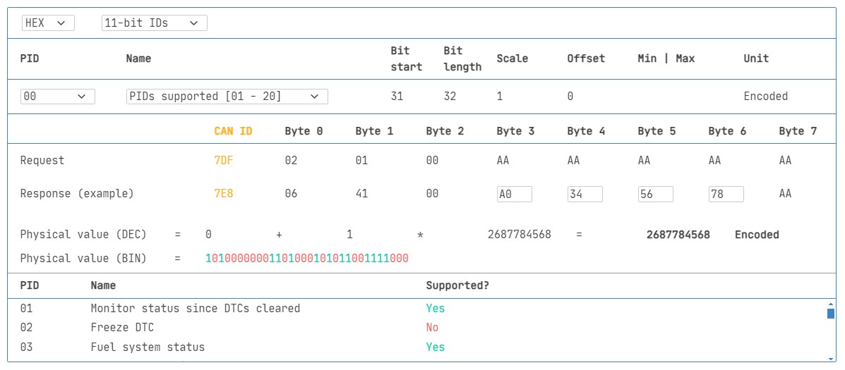
OBD2 PID Overview Tool: Interface of an OBD2 tool showing service 01, used to access real-time data parameters (PIDs).
OBD2 Data Logging via the Connector
Beyond basic diagnostics, the OBD2 connector is invaluable for data logging. Devices like CAN bus data loggers can connect to the OBD2 port to record vehicle data for various purposes:
- Performance Analysis: Track vehicle speed, RPM, acceleration, and other parameters for driving behavior analysis or performance tuning.
- Telematics and Fleet Management: Monitor vehicle location, engine health, and driver behavior for fleet optimization and vehicle tracking.
- Predictive Maintenance: Analyze logged data to identify potential maintenance needs before breakdowns occur.
- Vehicle Black Box Functionality: Record data in case of accidents or incidents for analysis and insurance purposes.
OBD2 Data Logger Request: Diagram illustrating OBD2 data logging with PID requests (0x7DF) and responses (0x7E8) over CAN bus.
Custom OBD2 Applications
The accessibility of the OBD2 connector has also spurred the development of custom applications:
- DIY Car Monitoring Dashboards: Enthusiasts create custom displays to monitor real-time vehicle data on tablets or smartphones.
- OBD2-based IoT Devices: Connecting vehicles to the Internet of Things (IoT) for advanced telematics, remote diagnostics, and connected car services.
- Research and Development: Engineers use OBD2 data for vehicle system analysis, algorithm development, and testing new automotive technologies.
Troubleshooting OBD2 Connector Issues
While the OBD2 connector is robust, issues can sometimes arise:
- Bent or Damaged Pins: Physical damage to the connector pins can prevent proper communication. Inspect the connector for bent or broken pins.
- Loose Connections: Ensure OBD2 devices are firmly plugged into the connector. A loose connection can lead to intermittent data or no communication.
- Connector Corrosion: In humid environments, corrosion can build up on the pins, hindering electrical contact. Use contact cleaner to clean corroded pins.
- Vehicle Electrical Issues: Problems with the vehicle’s electrical system, such as blown fuses or wiring faults, can affect the OBD2 connector’s functionality. Check vehicle fuses and wiring if you suspect electrical issues.
- Scanner Compatibility: Ensure your OBD2 scanner is compatible with your vehicle’s protocol. Not all scanners support all protocols or vehicle models perfectly.
Conclusion
The OBD2 connector pin diagram is the blueprint to understanding how to interface with your vehicle’s diagnostic system. From basic code reading with scanners to advanced data logging and custom applications, the 16-pin OBD2 connector is a vital gateway to automotive data. By understanding its pinouts, associated communication protocols, and practical uses, you can unlock a wealth of information and capabilities related to your vehicle. Whether you’re diagnosing a check engine light, monitoring performance data, or developing innovative automotive applications, the OBD2 connector and its pin diagram are your starting point.
Ready to explore more about OBD2 data logging? Check out our range of OBD2 data loggers and tools to take your vehicle diagnostics and data analysis to the next level.
Buy now Contact us