Experiencing a loose OBD2 port can be frustrating, interrupting your ability to diagnose car issues. Many car owners face this problem, and thankfully, it’s often a fixable DIY task. This guide, originally inspired by a repair on a 2004 RX-8, provides a step-by-step approach to securing your OBD2 connector, ensuring a reliable connection for diagnostics. While a complete Obd2 Connector Wiring Diagram isn’t strictly necessary for this physical repair, understanding the connector and its pins is helpful. Let’s get started on tightening up that loose OBD2 port.
First, the OBD2 port needs to be detached from its mounting bracket.
Understanding the OBD2 Port and Bracket Assembly
To remove the OBD2 port, you’ll notice plastic tabs on its sides that secure it to the bracket. By gently pressing these tabs inward, you can push the port upwards and release it. A helpful technique is to apply slight pressure to one side of the port against the bracket while manipulating the tab on the opposite side. This method often makes it easier to disengage the port. Here’s a closer view of these retaining tabs.
Close-up View of the OBD2 Connector Port Side Tabs
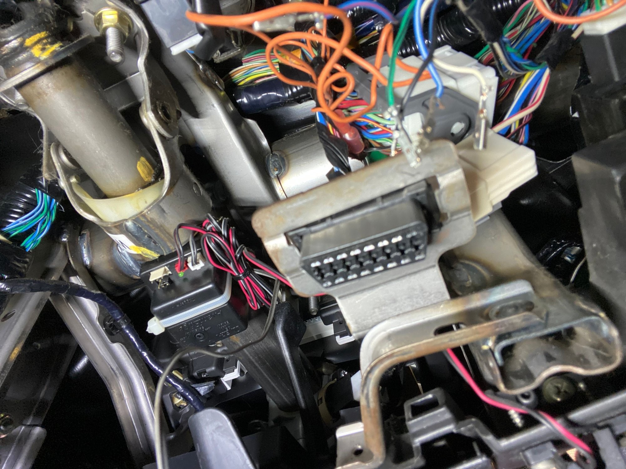
With the port now free from the bracket, you’ll see the back side where the wires connect. Before proceeding further, it’s crucial to document the wire colors and their positions. Taking pictures at this stage is highly recommended to ensure correct reassembly. Next, locate the white plastic locking piece that secures the wires within the connector. This piece needs to be removed to access the individual wire terminals.
Rear View of OBD2 Port Showing Wire Connections and White Locking Mechanism
In this image, a probe is shown lifting the white plastic bracket. By carefully prying this bracket upwards, you can detach it from the port housing. This action will release the individual wires, allowing you to work on each terminal.
Using a Probe to Release the White Locking Tab on the OBD2 Connector
Note that the end of the white tab is tucked under a black tab. You may need to slide your probe underneath to fully release it. The next step involves detaching the wires and their connectors. To do this, you’ll need a small probe to press a tiny plastic tab inside the port. When this tab is correctly pressed, the wire will release. Avoid using excessive force.
Pointing to the Internal Locking Tab for OBD2 Connector Wire Release
The image above highlights the location of this tab and indicates where to insert the probe for wire release. Once the wires are free, the key to fixing the loose connection is to re-tension the internal tabs within the connectors. These tabs make contact with the pins on your OBD2 scan tool. While a detailed OBD2 connector wiring diagram shows the function of each pin, for this repair, we are focusing on the physical connection.
Illustration of Re-bending the Internal Terminal within the OBD2 Connector
As shown in the diagram, insert your probe under the terminal tab and push inwards to slightly bend it upwards. This action increases the contact pressure against the OBD2 scanner pins. After re-tensioning each wire, carefully push them back into the port. You should feel a click as the terminal locks into place. Again, avoid forcing them. If a wire is difficult to insert, small bent-nose pliers can be helpful, but be careful not to bend the wire near the crimped area, as this can cause damage.
Recommended Probe Tools for OBD2 Connector Pin Adjustment
Specialized probes, like the blue set shown, including a bent probe, are ideal for this task. Standard probes might be less effective. These types of probes are readily available online.
While this repair is a cost-effective temporary solution, ideally, sourcing a new OBD2 port and terminals would be the best long-term fix. However, this DIY method can significantly improve the connection and get you back to diagnosing your vehicle effectively. For more in-depth understanding of the electrical connections, you might refer to an OBD2 connector wiring diagram to see how each pin is assigned, although it’s not strictly necessary for this mechanical repair.