Want to understand your car’s health through the Obd2 Data Stream?
This in-depth guide dives into the world of On-Board Diagnostics (OBD2) and its data stream, essential for modern automotive repair. We’ll explore the OBD2 protocol, connector, Parameter IDs (PIDs), and its integration with the CAN bus.
This isn’t just a basic overview – we’ll equip you with the knowledge to request and interpret OBD2 data, understand key applications of data logging, and provide practical tips for working with the OBD2 data stream.
Discover why this is becoming a go-to resource for mastering OBD2 and leveraging its data stream for vehicle diagnostics and performance analysis.
You can also check out our introductory video on OBD2 or download the PDF version for offline access.
Understanding the OBD2 System and Data Stream
OBD2 is essentially your car’s internal health monitoring system. It’s a standardized protocol designed to output a continuous obd2 data stream containing diagnostic trouble codes (DTCs) and a wealth of real-time operational data. This valuable stream of information is accessible through the standardized OBD2 connector.
You’ve likely encountered OBD2 in action before:
Ever seen the check engine light illuminate on your dashboard?
That’s the car’s OBD2 system signaling a potential issue. When you take your car to a mechanic, they utilize an OBD2 scanner to pinpoint the problem.
This process involves connecting the OBD2 scanner to the 16-pin OBD2 connector, typically located near the steering wheel. The scanner sends ‘OBD2 requests’ to the vehicle, and the car responds with an obd2 data stream. This stream includes parameters like speed, fuel level, and Diagnostic Trouble Codes (DTCs), enabling faster and more efficient troubleshooting.
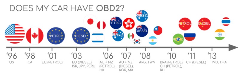
OBD2 Compatibility: Is Your Car Equipped?
The answer is likely yes!
The vast majority of modern gasoline and diesel cars, excluding electric vehicles, are OBD2 compliant and often operate on the CAN bus network. For older vehicles, even if a 16-pin OBD2 connector is present, it might not fully support the OBD2 protocol. A reliable way to check compliance is based on the vehicle’s manufacturing date and region of sale:
A Look at OBD2 History
OBD2’s origins are in California. The California Air Resources Board (CARB) mandated OBD in all new vehicles from 1991 onwards, primarily for emission control.
The Society of Automotive Engineers (SAE) further refined this by recommending the OBD2 standard, standardizing DTCs and the OBD connector across different manufacturers (SAE J1962).
The OBD2 standard was progressively implemented:
- 1996: OBD2 becomes mandatory in the USA for cars and light trucks.
- 2001: Required in the EU for gasoline cars.
- 2003: EU mandate extends to diesel cars (EOBD).
- 2005: OBD2 becomes mandatory in the US for medium-duty vehicles.
- 2008: US vehicles must adopt ISO 15765-4 (CAN) as the foundation for OBD2 communication.
- 2010: OBD2 requirement extends to heavy-duty vehicles in the US.
The Future of OBD2 and Data Streaming
OBD2 is firmly established, but its evolution is ongoing. Let’s examine key future trends impacting the obd2 data stream:
Initially designed for emissions monitoring, legislated OBD2 faces a challenge with electric vehicles. EVs aren’t obligated to support OBD2, and most modern EVs indeed bypass standard OBD2 requests. Instead, they often use OEM-specific UDS communication protocols. This makes accessing the obd2 data stream from EVs difficult without reverse engineering efforts. However, some progress is being made, as seen in case studies for electric cars like Tesla, Hyundai/Kia, Nissan, and VW/Skoda EVs.
Current OBD2 implementations have limitations in data richness and underlying communication protocols. Modern alternatives are emerging, such as WWH-OBD (World Wide Harmonized OBD) and OBDonUDS (OBD on UDS). These aim to improve OBD communication by utilizing the UDS protocol. For more on this, explore our introduction to UDS.
In our connected world, manual OBD2 testing for emissions seems outdated. The proposed solution? OBD3: Integrating telematics into all vehicles.
OBD3 envisions adding a small radio transponder to cars, similar to those used for bridge tolls. This would allow the car’s vehicle identification number (VIN) and DTCs to be wirelessly transmitted to a central server for automated monitoring.
Many devices already facilitate transferring CAN or OBD2 data via WiFi/cellular, such as the CANedge2 WiFi CAN logger and the CANedge3 3G/4G CAN logger.
While efficient and cost-saving, OBD3 raises privacy concerns due to potential surveillance implications.
Originally intended for stationary emission checks, OBD2’s data stream is now widely used by third parties for real-time data acquisition via OBD2 dongles, CAN loggers and more. However, the German car industry is seeking to restrict this access (link to article).
BMW’s SVP Electronics, Christoph Grote, stated in 2017:
“OBD has been designed to service cars in repair shops. In no way has it been intended to allow third parties to build a form of data-driven economy on the access through this interface“
The proposal is to disable OBD2 functionality during driving and instead centralize data collection with manufacturers. This would give manufacturers control over the burgeoning ‘automotive big data’.
Arguments for this shift cite security benefits, such as reducing the risk of car hacking. However, critics view it as a commercially motivated move (link to article). Whether this trend gains traction remains to be seen, but it could significantly disrupt the market for third-party OBD2 services and obd2 data stream applications.
Become a CAN Bus Expert with Our Ultimate Guide
Ready to master CAN bus technology?
Access 12 comprehensive introductions in our 160+ page PDF guide:
Download now
OBD2 Standards and Protocols
On-board diagnostics, OBD2, operates as a higher-layer protocol, similar to a language, while CAN acts as the communication method, like a phone line. This places OBD2 alongside other CAN-based higher-layer protocols such as J1939, CANopen, and NMEA 2000.
OBD2 standards define the OBD2 connector, lower-layer protocols, OBD2 Parameter IDs (PIDs), and more, ensuring a consistent obd2 data stream.
These standards can be mapped to the 7-layer OSI model. Notably, both SAE and ISO standards cover several layers. This reflects the standards defined in the USA (SAE) and EU (ISO). Many standards are technically very similar, such as SAE J1979 and ISO 15031-5, or SAE J1962 and ISO 15031-3.
The OBD2 Connector: SAE J1962 Standard
The 16-pin OBD2 connector, standardized under SAE J1962 / ISO 15031-3, provides easy access to your car’s obd2 data stream. It’s also known as the Data Link Connector (DLC).
The illustration shows a typical Type A OBD2 pin connector. Key points to remember:
- The connector is usually near the steering wheel, but its location can vary and may be hidden.
- Pin 16 provides battery power, often even when the ignition is off.
- The OBD2 pinout is protocol-dependent.
- CAN bus is the most prevalent lower-layer protocol, so pins 6 (CAN-H) and 14 (CAN-L) are commonly used.
OBD2 Connector Types: A vs. B
You might encounter both Type A and Type B OBD2 connectors. Type A is standard in cars, while Type B is more common in medium and heavy-duty vehicles.
While both types have similar pinouts, they differ in power supply: Type A provides 12V, and Type B provides 24V. Baud rates can also vary, with cars typically using 500K and heavy-duty vehicles often using 250K (with increasing support for 500K).
Type B connectors have a central interrupted groove, making a Type B OBD2 adapter cable compatible with both Type A and B sockets. However, a Type A adapter will not fit into a Type B socket.
OBD2 and CAN Bus Integration: ISO 15765-4
Since 2008, ISO 15765 has mandated CAN bus as the lower-layer protocol for OBD2 in all US vehicles.
ISO 15765-4 (Diagnostics over CAN or DoCAN) specifies how the CAN standard (ISO 11898) is used for diagnostics. It standardizes the CAN interface for testing equipment, focusing on the physical, data link, and network layers:
- CAN bus bit-rate must be either 250K or 500K.
- CAN IDs can be 11-bit or 29-bit.
- Specific CAN IDs are designated for OBD requests and responses.
- Diagnostic CAN frame data length is fixed at 8 bytes.
- OBD2 adapter cable length must not exceed 5 meters.
OBD2 CAN Identifiers: 11-bit and 29-bit
OBD2 communication relies on request/response message exchanges within the obd2 data stream.
Most cars use 11-bit CAN IDs for OBD2. The ‘Functional Addressing’ ID, 0x7DF, broadcasts a request to all OBD2-compatible ECUs to report data for the requested parameter (ISO 15765-4). CAN IDs 0x7E0-0x7E7 enable ‘Physical Addressing’ requests to specific ECUs (less common).
ECUs respond with 11-bit IDs in the range 0x7E8-0x7EF. The most common response ID is 0x7E8 (ECM, Engine Control Module), followed by 0x7E9 (TCM, Transmission Control Module).
Some vehicles, particularly vans and medium/heavy-duty vehicles, may use extended 29-bit CAN identifiers for OBD2 communication.
Here, the ‘Functional Addressing’ CAN ID is 0x18DB33F1.
Responses use CAN IDs ranging from 0x18DAF100 to 0x18DAF1FF (typically 18DAF110 and 18DAF11E). This response ID is sometimes represented in ‘J1939 PGN’ format, specifically PGN 0xDA00 (55808), which is reserved for ISO 15765-2 in the J1939-71 standard.
OBD2 vs. Proprietary CAN Protocols
It’s crucial to understand that vehicle ECUs operate using proprietary CAN protocols developed by the original equipment manufacturer (OEM), independent of OBD2. These protocols are often specific to vehicle brand, model, and year. Accessing and interpreting this proprietary data usually requires reverse engineering unless you are the OEM.
Connecting a CAN bus data logger to the OBD2 connector might capture OEM-specific CAN data, typically broadcast at high rates (1000-2000 frames/second). However, newer vehicles often have a ‘gateway’ that restricts OBD2 connector access to OBD2 communication only, blocking proprietary CAN data.
Think of OBD2 as an ‘additional’ higher-layer protocol that runs alongside the OEM-specific protocol. The obd2 data stream is a standardized window into vehicle data, separate from the comprehensive OEM data network.
Bit-rate and ID Validation for OBD2 Data Stream
As mentioned, OBD2 can use two bit-rates (250K, 500K) and two CAN ID lengths (11-bit, 29-bit), resulting in four possible combinations. Modern cars commonly use 500K and 11-bit IDs, but tools should systematically verify this.
ISO 15765-4 outlines an initialization sequence to determine the correct combination. This relies on the fact that OBD2-compliant vehicles must respond to a mandatory OBD2 request (see OBD2 PID section) and that incorrect bit-rates cause CAN error frames.
Newer ISO 15765-4 versions consider vehicles that may support OBD communication via OBDonUDS instead of OBDonEDS. This article primarily focuses on OBD2/OBDonEDS (OBD on Emission Diagnostic Service per ISO 15031-5/SAE J1979) versus WWH-OBD/OBDonUDS (OBD on Unified Diagnostic Service per ISO 14229, ISO 27145-3/SAE J1979-2).
To distinguish between OBDonEDS and OBDonUDS, testing tools can send UDS requests with 11-bit/29-bit functional address IDs for service 0x22 and data identifier (DID) 0xF810 (protocol identification). Vehicles supporting OBDonUDS should have ECUs that respond to this DID.
OBDonEDS (aka OBD2, SAE OBD, EOBD, or ISO OBD) is prevalent in most non-EV cars, while WWH-OBD is mainly used in EU trucks/buses.
Five Lower-Layer OBD2 Protocols
While CAN (ISO 15765) is now dominant for OBD2, especially in vehicles post-2008, older cars might use one of four other lower-layer protocols. Understanding these and their pinouts is helpful when working with older vehicles:
- ISO 15765 (CAN bus): Mandatory in US cars since 2008 and widely used today.
- ISO 14230-4 (KWP2000): Keyword Protocol 2000, common in 2003+ cars, particularly in Asia.
- ISO 9141-2: Used in EU, Chrysler, and Asian cars around 2000-2004.
- SAE J1850 (VPW): Primarily used in older GM vehicles.
- SAE J1850 (PWM): Primarily used in older Ford vehicles.
ISO-TP for OBD2 Message Transport: ISO 15765-2
All obd2 data stream communication on CAN bus uses ISO-TP (ISO 15765-2), a transport protocol enabling payloads larger than 8 bytes. This is crucial for OBD2 functions like retrieving the Vehicle Identification Number (VIN) or Diagnostic Trouble Codes (DTCs). ISO 15765-2 handles segmentation, flow control, and reassembly of these larger messages. For detailed information, refer to our UDS protocol introduction.
Often, OBD2 data fits within a single CAN frame. In such cases, ISO 15765-2 specifies ‘Single Frame’ (SF) usage. The first data byte (PCI field) indicates the payload length (excluding padding), leaving 7 bytes for OBD2 communication within the obd2 data stream.
Decoding the OBD2 Diagnostic Message: SAE J1979, ISO 15031-5
To effectively work with the obd2 data stream over CAN, let’s break down a raw ‘Single Frame’ OBD2 CAN message. In simplified terms, it comprises an identifier, data length (PCI field), and data. The data section is further divided into Mode, Parameter ID (PID), and data bytes.
Example: OBD2 Request and Response
Consider this request/response example for ‘Vehicle Speed’ parameter within the obd2 data stream:
An external tool sends a request to the car with CAN ID 0x7DF and 2 payload bytes: Mode 0x01 and PID 0x0D. The car responds via CAN ID 0x7E8 with 3 payload bytes, including the Vehicle Speed value in the 4th byte, 0x32 (decimal 50).
Using OBD2 PID 0x0D decoding rules, we determine the physical value is 50 km/h.
Next, we’ll explore OBD2 modes and PIDs to further understand the obd2 data stream.
The 10 OBD2 Services (Modes)
There are 10 standardized OBD2 diagnostic services, or modes. Mode 0x01 provides current real-time data, while others handle diagnostic trouble codes (DTCs) or freeze frame data within the obd2 data stream.
Vehicles are not required to support all 10 OBD2 modes and may also implement OEM-specific modes beyond these standards.
In OBD2 messages, the mode is the 2nd byte. In requests, the mode is directly included (e.g., 0x01), while in responses, 0x40 is added to the mode value (e.g., resulting in 0x41).
OBD2 Parameter IDs (PIDs) and Data Stream
Each OBD2 mode contains Parameter IDs (PIDs). Mode 0x01, for example, includes approximately 200 standardized PIDs for real-time data such as speed, RPM, and fuel level within the obd2 data stream. However, vehicles typically support only a subset of these PIDs.
One PID is particularly important:
If an emissions-related ECU supports any OBD2 services, it must support mode 0x01 PID 0x00. Responding to PID 0x00, the ECU indicates support for PIDs 0x01-0x20. This makes PID 0x00 a fundamental ‘OBD2 compatibility test’. Similarly, PIDs 0x20, 0x40, …, 0xC0 can be used to check support for subsequent mode 0x01 PID ranges within the obd2 data stream.
Tip: OBD2 PID Overview Tool
SAE J1979 and ISO 15031-5 appendices provide scaling information for standard OBD2 PIDs, enabling conversion of raw data to physical values (as explained in our CAN bus introduction).
For quick lookup of mode 0x01 PIDs, use our OBD2 PID overview tool. It helps construct OBD2 request frames and dynamically decode OBD2 responses from the obd2 data stream.
OBD2 PID overview tool
Logging and Decoding OBD2 Data Stream: A Practical Guide
This section provides a practical example of logging obd2 data stream using the CANedge CAN bus data logger.
The CANedge allows custom CAN frame transmission, making it suitable for OBD2 data logging and capturing the obd2 data stream.
Connect the CANedge to your vehicle using our OBD2-DB9 adapter cable for easy setup.
[Caption: You can send a CAN frame at e.g. 500K, then check if it is successfully sent]
[Caption: The responses to ‘Supported PIDs’ can be reviewed in asammdf]
[Caption: ‘Supported PIDs’ results can be decoded via our OBD2 PID lookup tool]
#1: Bit-rate, ID, and Supported PID Validation
ISO 15765-4 details how to determine the correct bit-rate and IDs for a specific vehicle to properly capture the obd2 data stream. Use the CANedge to perform these tests (see CANedge Intro for details):
- Send a CAN frame at 500K and check for success (if unsuccessful, try 250K).
- Use the validated bit-rate for subsequent communication.
- Send multiple ‘Supported PIDs’ requests and analyze the responses.
- Determine 11-bit vs. 29-bit IDs based on response IDs.
- Identify supported PIDs from the response data, understanding the scope of the obd2 data stream available.
We provide plug-and-play configurations for these tests. Most 2008+ non-EV cars support 40-80 PIDs via 500K bit-rate, 11-bit CAN IDs, and the OBD2/OBDonEDS protocol.
The asammdf GUI screenshot shows multiple responses to a single OBD request because the 0x7DF request ID polls all ECUs. Since all OBD2/OBDonEDS-compliant ECUs must support service 0x01 PID 0x00, many responses to this PID are common. Subsequent ‘Supported PIDs’ requests receive fewer ECU responses. Notably, the ECM ECU (0x7E8) supports all PIDs supported by other ECUs in this example. Reducing busload can be achieved by directing subsequent requests to the ECM using ‘Physical Addressing’ CAN ID 0x7E0.
#2: Configuring OBD2 PID Requests for Data Streaming
After identifying supported PIDs, bit-rate, and CAN IDs, configure your transmit list with desired PIDs to capture the obd2 data stream.
Consider these points:
- CAN IDs: Use ‘Physical Addressing’ request IDs (e.g., 0x7E0) to avoid multiple responses per request, streamlining the obd2 data stream.
- Spacing: Add 300-500 ms intervals between OBD2 requests to prevent ECU overload and ensure reliable responses within the obd2 data stream.
- Battery Drain: Use triggers to stop transmissions when the vehicle is inactive, preventing ECU ‘wake-up’ and battery drain during obd2 data stream capture.
- Filters: Add filters to record only OBD2 responses if OEM-specific CAN data is also present, focusing the obd2 data stream capture.
With configuration complete, the device is ready to log raw OBD2 data and capture the vehicle’s obd2 data stream!
[Caption: An example list of CANedge OBD2 PID requests]
[Caption: asammdf lets you DBC decode and visualize OBD2 data]
#3: DBC Decoding of Raw OBD2 Data Stream
To analyze and visualize logged data, decode the raw obd2 data stream into ‘physical values’ (e.g., km/h, °C).
Decoding information is in ISO 15031-5/SAE J1979 and online resources like Wikipedia. We offer a free OBD2 DBC file for easy DBC decoding in most CAN bus software tools.
Decoding OBD2 data is more complex than standard CAN signals. Different OBD2 PIDs use the same CAN ID (e.g., 0x7E8). CAN ID alone isn’t enough to identify signals in the payload within the obd2 data stream.
Signal identification requires using the CAN ID, OBD2 mode, and OBD2 PID. This ‘extended multiplexing’ is implementable in DBC files.
CANedge: Your OBD2 Data Stream Logger
The CANedge easily records obd2 data stream to an 8-32 GB SD card. Connect to a car/truck to start logging and decode data using free software/APIs and our OBD2 DBC.
OBD2 logger intro
CANedge
OBD2 Multi-Frame Examples and Data Stream Complexity: ISO-TP
All obd2 data stream communication utilizes ISO-TP (ISO 15765-2). Most examples so far are single-frame. This section shows multi-frame communication examples, demonstrating the intricacies of the obd2 data stream.
Multi-frame OBD2 needs flow control frames (see our UDS intro). A static flow control frame can be transmitted ~50 ms after the initial request, as shown in the CANedge configuration example.
Multi-frame OBD2 responses require CAN software/API tools with ISO-TP support, like CANedge MF4 decoders, to properly capture and interpret the complete obd2 data stream.
Example 1: OBD2 Vehicle Identification Number (VIN) from Data Stream
The Vehicle Identification Number (VIN) is crucial for telematics, diagnostics, and more (see our UDS intro). To retrieve the VIN using OBD2 requests and the obd2 data stream, use mode 0x09 and PID 0x02:
The tester tool sends a Single Frame request with PCI field (0x02), request service identifier (0x09), and PID (0x02).
The vehicle responds with a First Frame containing PCI, length (0x014 = 20 bytes), mode (0x49, i.e., 0x09 + 0x40), and PID (0x02). Following the PID is byte 0x01 (Number Of Data Items – NODI), in this case 1 (ISO 15031-5 / SAE J1979). The remaining 17 bytes are the VIN, convertible from HEX to ASC (UDS intro).
Example 2: OBD2 Multi-PID Request (6x) and Data Stream Efficiency
External tools can request up to 6 mode 0x01 OBD2 PIDs in a single request frame to optimize obd2 data stream retrieval. The ECU responds with data for supported PIDs (skipping unsupported ones), potentially across multiple frames (ISO-TP).
This improves data collection frequency and efficiency. However, signal encoding becomes request-method-specific, making generic OBD2 DBC files less useful. We advise against this method in practice. Below is an example trace:
The multi-frame response is similar to the VIN example, but the payload includes requested PIDs and their data. PIDs are often ordered as requested (common, but not ISO 15031-5 standard).
Decoding this via DBC files is difficult. Avoid this approach for practical data logging unless using tools with built-in support. It’s a complex ‘extended multiplexing’ case, with payload PID positions varying, making DBC generalization across vehicles with differing supported PIDs very challenging. Managing multiple multi-PID requests via DBC manipulations becomes nearly impossible.
Workarounds include custom scripts and recording transmit messages to interpret responses based on requests. However, these approaches are hard to scale.
Example 3: OBD2 Diagnostic Trouble Codes (DTCs) in the Data Stream
Use OBD2 mode 0x03 (‘Show stored Diagnostic Trouble Codes’) to request emissions-related DTCs from the obd2 data stream. No PID is in the request. Responding ECUs report the number of stored DTCs (possibly 0), with each DTC using 2 data bytes. Multi-frame responses are needed for more than 2 DTCs.
The 2-byte DTC value is split (ISO 15031-5/ISO 15031-6). The first 2 bits define ‘category’, and the remaining 14 bits form a 4-digit hex code (see visual). Decoded DTC values can be looked up using OBD2 DTC lookup tools like repairpal.com.
The example below shows a request to an ECU with 6 stored DTCs within the obd2 data stream.
OBD2 Data Logging Use Cases and the Power of Data Stream
OBD2 data from cars and light trucks has diverse applications, leveraging the real-time obd2 data stream:
Logging Car Data for Insights
OBD2 data logging can reduce fuel costs, improve driving habits, test prototype parts, and inform insurance models by analyzing the obd2 data stream.
obd2 logger
Real-Time Car Diagnostics and Data Streaming
OBD2 interfaces enable real-time streaming of human-readable OBD2 data, facilitating immediate vehicle issue diagnosis from the obd2 data stream.
obd2 streaming
Predictive Maintenance through OBD2 Data Stream
IoT OBD2 loggers monitor car and light truck obd2 data streams in the cloud to predict and prevent breakdowns.
predictive maintenance
Vehicle Blackbox Logger Using OBD2 Data Stream
An OBD2 logger acts as a ‘black box’ for vehicles or equipment, providing data for disputes or diagnostics by recording the continuous obd2 data stream.
can bus blackbox
Have an OBD2 data logging use case? Contact us for expert consultation!
Contact us
Explore our guides section for more introductions or download the ‘Ultimate Guide’ PDF.
Need to log or stream OBD2 data?
Get your OBD2 data logger today!
Buy now
Contact us
Recommended for You
OBD2 DATA LOGGER: EASILY LOG & CONVERT OBD2 DATA
CANEDGE2 – PRO CAN IoT LOGGER
CAN BUS INTERFACE: STREAMING OBD2 DATA WITH SAVVYCAN