Looking for detailed Obd2 Info?
This guide provides an in-depth exploration of the On-Board Diagnostics 2 (OBD2) protocol, covering everything from the OBD2 connector and Parameter IDs (PIDs) to its connection with the CAN bus system.
Note: This is a comprehensive guide, designed to elevate your understanding of OBD2. You’ll learn not only the fundamentals but also how to effectively request and interpret OBD2 data, explore crucial logging applications, and gain practical insights.
Discover why this is quickly becoming the go-to resource for OBD2 information.
You can also check out our introductory OBD2 video above – or download the PDF version for offline access.
Article Contents:
Author: Martin Falch (Updated January 2025)
Download as PDF
What is OBD2? – Unpacking the OBD2 Info
OBD2, or On-Board Diagnostics 2, is essentially your vehicle’s integrated health monitoring system. It’s a standardized protocol that enables the extraction of crucial diagnostic trouble codes (DTCs) and real-time operational data through the OBD2 connector. This system is designed to provide valuable OBD2 info directly from your vehicle’s computer.
You’ve likely already encountered OBD2 in action, perhaps without even realizing it.
Ever seen the Check Engine Light illuminate on your dashboard?
That’s your car’s way of communicating a potential issue. When you take your vehicle to a mechanic, they utilize an OBD2 scanner to pinpoint the problem. This scanner is the key to accessing OBD2 info.
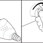
To perform diagnostics, the mechanic connects the OBD2 reader to the OBD2 16-pin connector, typically located near the steering wheel. The diagnostic tool transmits ‘OBD2 requests’ to the car’s computer, and the car responds with ‘OBD2 responses’. These responses can contain a wealth of OBD2 info, including parameters like speed, fuel level, and Diagnostic Trouble Codes (DTCs). This real-time data stream of OBD2 info allows for much faster and more accurate troubleshooting of vehicle issues.
Alt text: Understanding OBD2: The Malfunction Indicator Light (MIL) illuminates when the On-Board Diagnostics system detects an issue, prompting the use of an OBD2 scan tool for diagnosis.
OBD2 Compatibility: Does Your Car Have It? – Finding OBD2 Info for Your Vehicle
In most cases, the answer is: Yes, probably! Getting OBD2 info from your car is generally straightforward for modern vehicles.
The vast majority of modern non-electric cars are equipped with OBD2 and often operate on the CAN bus protocol. However, for older vehicles, even if a 16-pin OBD2 connector is present, it might not actually support the OBD2 protocol. To determine OBD2 compliance, a key factor is where and when the vehicle was initially purchased:
Alt text: OBD2 Compliance Guide: Check if your car is OBD2 compliant based on the region (EU/US) and year of purchase for vehicles with gasoline or diesel engines.
A Look at OBD2 History – The Evolution of OBD2 Info
The story of OBD2 begins in California, driven by the California Air Resources Board (CARB). In their pursuit of stricter emission control, CARB mandated the inclusion of OBD systems in all new cars starting from 1991. This marked the beginning of standardized OBD2 info for vehicle emissions.
The OBD2 standard itself was developed and recommended by the Society of Automotive Engineers (SAE). They played a crucial role in standardizing DTCs and the physical OBD connector across different vehicle manufacturers (SAE J1962). This standardization was vital for making OBD2 info universally accessible.
From its Californian origins, the OBD2 standard was progressively implemented across the automotive industry:
- 1996: OBD2 became mandatory in the USA for cars and light trucks.
- 2001: The EU mandated OBD2 for gasoline cars.
- 2003: The mandate extended in the EU to include diesel cars (EOBD – European On-Board Diagnostics).
- 2005: OBD2 was required in the US for medium-duty vehicles.
- 2008: US regulations stipulated that cars must utilize ISO 15765-4 (CAN) as the foundation for OBD2 communication, further standardizing OBD2 info transfer.
- 2010: Finally, OBD2 compliance became mandatory in the US for heavy-duty vehicles, completing the rollout across vehicle classes.
Alt text: OBD2 Historical Timeline: Illustrating the evolution of OBD2 from emission control origins to its integration with car data systems and the CAN bus network.
Alt text: OBD2 History Timeline: A visual overview of the key milestones in the history of On-Board Diagnostics 2, highlighting its progressive implementation and standardization.
Alt text: The Future of OBD: OBD3 envisions remote diagnostics, emissions testing, and cloud integration through IoT, enhancing vehicle monitoring and data accessibility.
The Future of OBD2 – What’s Next for OBD2 Info?
OBD2 is firmly established in automotive diagnostics, but its future form is evolving. Understanding these trends is crucial for staying informed about OBD2 info.
Here are some key trends shaping the future of OBD2 and access to OBD2 info:
Initially, legislated OBD2 was primarily intended for emissions control and testing. Consequently, electric vehicles (EVs) are not obligated to support OBD2 in its traditional form. In fact, most modern EVs do not support standard OBD2 requests. Instead, they predominantly use OEM-specific UDS (Unified Diagnostic Services) communication protocols. This OEM-specific approach often makes it challenging to decode data from EVs unless the decoding rules have been reverse-engineered. However, there are successful cases of reverse engineering providing access to OBD2 info in EVs, as demonstrated in our case studies for electric cars. These include projects focused on Tesla, Hyundai/Kia, Nissan, and VW/Skoda EVs, where researchers have managed to tap into valuable OBD2 info.
Today, OBD2 implementations vary, and it faces limitations in areas like data richness and the underlying communication protocols. To address these limitations, advanced alternatives have emerged, including WWH-OBD (World-Wide Harmonized OBD) and OBDonUDS (OBD on UDS). Both of these protocols aim to modernize and improve OBD communication by building upon the UDS protocol. For more detailed OBD2 info on these advanced protocols, refer to our introduction to UDS.
In our increasingly connected world, conventional OBD2 testing methods can seem outdated. Manual emissions checks are both time-consuming and costly.
The proposed solution? OBD3 – integrating telematics into all vehicles.
Essentially, OBD3 envisions adding a small radio transponder (similar to those used for bridge tolls) to every car. This transponder would enable the car’s Vehicle Identification Number (VIN) and DTCs to be transmitted wirelessly via WiFi to a central server for automated checks. This would streamline access to OBD2 info and simplify regulatory compliance.
Many devices already facilitate the wireless transmission of CAN or OBD2 data via WiFi or cellular networks. Examples include the CANedge2 WiFi CAN logger and the CANedge3 3G/4G CAN logger. These devices highlight the feasibility of wireless OBD2 info transfer.
While this approach offers cost savings and convenience, it also raises political and social challenges related to surveillance and data privacy. The widespread collection and transmission of OBD2 info could be perceived as an intrusion on personal freedoms.
The OBD2 protocol was originally designed for stationary emission controls.
However, today, OBD2 is extensively used by third parties to generate real-time vehicle data through OBD2 dongles, CAN loggers and similar devices. This broader use of OBD2 info is now being challenged by the German car industry:
OBD was designed for car servicing in repair shops. It was never intended to allow third parties to build a data-driven economy based on access through this interface.“
– Christoph Grote, SVP Electronics, BMW (2017)
The industry proposal is to potentially “disable” OBD2 functionality while the vehicle is in motion. Instead, vehicle data would be centrally collected by the manufacturers. This shift would effectively give manufacturers control over the burgeoning field of ‘automotive big data’. This change could significantly restrict third-party access to OBD2 info.
The rationale is often framed around security concerns, such as mitigating the risk of car hacking. However, many observers view this as a commercially motivated move. Whether this trend gains traction remains to be seen, but it has the potential to significantly disrupt the market for third-party OBD2 services and access to OBD2 info.
Alt text: Future OBD Challenges: Electric Vehicles may limit OBD2 access, potentially blocking standard data retrieval through the OBD2 connector in favor of proprietary systems.
Get Our ‘Ultimate CAN Guide’
Want to become an expert in CAN bus technology and expand your OBD2 info knowledge?
Access our 12 ‘simple introductions’ in one comprehensive 160+ page PDF:
Download now
OBD2 Standards – Decoding the Framework of OBD2 Info
On-board diagnostics, specifically OBD2, operates as a higher-layer protocol, similar to a language in communication systems. In contrast, CAN (Controller Area Network) functions as the communication medium, comparable to a telephone line. This hierarchical structure positions OBD2 alongside other CAN-based higher-layer protocols such as J1939, CANopen, and NMEA 2000. Understanding these standards is key to interpreting OBD2 info correctly.
Specifically, OBD2 standards define the specifications for the OBD2 connector, the lower-layer communication protocols, OBD2 Parameter IDs (PIDs), and other critical aspects of the diagnostic system.
These standards can be organized using the 7-layer OSI model, which provides a framework for understanding network communication. In the following sections, we will concentrate on the most significant standards relevant to OBD2 info.
In the OSI model representation, you’ll notice that several layers are addressed by both SAE (Society of Automotive Engineers) and ISO (International Organization for Standardization) standards. This dual coverage generally reflects the standardization efforts for OBD systems in the USA (SAE) and Europe (ISO). Notably, many of these standards are technically very similar, such as SAE J1979, which is analogous to ISO 15031-5, and SAE J1962, which corresponds to ISO 15031-3. This harmonization ensures a degree of global consistency in OBD2 info and diagnostics.
Alt text: OBD2 and CAN Bus in OSI Model: Illustrating the relationship between OBD2 and CAN Bus within the 7-layer OSI model, highlighting relevant ISO and SAE standards like ISO 15765 and ISO 11898.
Alt text: OBD2 Connector Pinout Type A: Diagram of a Type A OBD2 connector, detailing the pin assignments for a female socket, also known as a Data Link Connector (DLC).
The OBD2 Connector [SAE J1962] – Physical Interface for OBD2 Info
The 16-pin OBD2 connector is your gateway to accessing OBD2 info from your vehicle. Its specifications are meticulously defined in the standard SAE J1962 / ISO 15031-3. This connector is the physical point of access for retrieving OBD2 info.
The illustration above shows a typical Type A OBD2 pin connector, sometimes referred to as the Data Link Connector (DLC).
Key points to note about the OBD2 connector and its role in accessing OBD2 info:
- The connector is usually located near the steering wheel, but its exact location can be concealed depending on the vehicle model.
- Pin 16 provides battery power, often remaining active even when the ignition is switched off, ensuring continuous power for certain OBD2 functions.
- The OBD2 pinout configuration is dependent on the specific communication protocol used by the vehicle.
- The most prevalent lower-layer protocol is CAN bus, meaning that pins 6 (CAN-High) and 14 (CAN-Low) are typically connected in most OBD2 implementations for CAN-based OBD2 info transmission.
OBD2 Connector Types: A vs. B – Variations in OBD2 Info Access
In practical applications, you may encounter both Type A and Type B OBD2 connectors. Type A is commonly found in passenger cars and light-duty vehicles, while Type B is more prevalent in medium and heavy-duty vehicles. The type of connector can influence how OBD2 info is accessed.
As illustrated, both connector types share similar OBD2 pinouts but differ primarily in their power supply outputs. Type A typically provides a 12V power supply, whereas Type B is designed for 24V systems. Additionally, the communication baud rate can vary, with passenger cars often using 500 Kbps, while heavy-duty vehicles commonly use 250 Kbps (although newer heavy-duty vehicles are increasingly supporting 500 Kbps as well). These differences impact the transmission of OBD2 info.
To visually distinguish between the two OBD2 socket types, note that the Type B OBD2 connector features an interrupted groove in the center. This physical difference has practical implications for connector compatibility. A Type B OBD2 adapter cable is designed to be compatible with both Type A and Type B sockets, providing versatile OBD2 info access. However, a Type A connector will not physically fit into a Type B socket due to the groove difference.
Alt text: OBD2 Connector Types A and B: A comparison of Type A and Type B OBD2 connectors as defined by SAE J1962, highlighting differences in 12V/24V power supply and typical vehicle applications (cars, vans, trucks).
Alt text: OBD2 vs CAN Bus ISO 15765: Diagram illustrating the relationship between OBD2 protocol and CAN bus according to ISO 15765 standards, showing CAN bus as the physical layer for OBD2 communication.
OBD2 and CAN Bus [ISO 15765-4] – The Communication Backbone for OBD2 Info
Since 2008, CAN bus has become the mandatory lower-layer protocol for OBD2 in all vehicles sold in the US, as mandated by ISO 15765. This standard ensures consistent OBD2 info exchange across vehicles.
ISO 15765-4, also known as Diagnostics over CAN (or DoCAN), specifies a set of constraints and guidelines applied to the CAN standard (ISO 11898). It standardizes the CAN interface specifically for diagnostic test equipment, focusing on the physical, data link, and network layers to ensure reliable OBD2 info transfer.
Key specifications defined by ISO 15765-4 for CAN-based OBD2 info communication include:
- The CAN bus bit rate must be either 250 Kbps or 500 Kbps, providing flexibility while maintaining standard speeds.
- CAN IDs can be either 11-bit or 29-bit, accommodating both standard and extended CAN addressing schemes.
- Specific CAN IDs are reserved for OBD requests and responses, ensuring proper routing of OBD2 info.
- The diagnostic CAN frame data length is fixed at 8 bytes, optimizing data transmission efficiency.
- The OBD2 adapter cable must have a maximum length of 5 meters, limiting signal degradation and ensuring reliable OBD2 info retrieval.
OBD2 CAN Identifiers (11-bit, 29-bit) – Addressing and Routing OBD2 Info
All OBD2 communication, and thus all OBD2 info exchange, is structured around request and response message pairs. These messages use specific CAN identifiers to ensure proper routing and handling within the vehicle network.
In most passenger cars, 11-bit CAN IDs are used for OBD2 communication. Within this scheme, the ‘Functional Addressing’ ID is 0x7DF. This ID is used to broadcast a request to all OBD2-compliant Electronic Control Units (ECUs) in the vehicle, asking if they have data to report for the requested parameter, as defined in ISO 15765-4. In contrast, CAN IDs in the range of 0x7E0 to 0x7E7 can be used for ‘Physical Addressing’ requests, which target specific ECUs directly. Physical addressing is less commonly used in typical OBD2 info requests but is available for more targeted diagnostics.
ECUs respond to requests using 11-bit IDs in the range of 0x7E8 to 0x7EF. The most common response ID is 0x7E8, which typically comes from the ECM (Engine Control Module). Another frequently used response ID is 0x7E9, often associated with the TCM (Transmission Control Module). These response IDs are crucial for correctly interpreting OBD2 info.
In some vehicle types, particularly vans and light, medium, and heavy-duty vehicles, OBD2 communication may utilize extended 29-bit CAN identifiers instead of the 11-bit IDs. This is an alternative addressing scheme for transmitting OBD2 info.
When 29-bit identifiers are used, the ‘Functional Addressing’ CAN ID is 0x18DB33F1. This serves the same broadcast function as 0x7DF in 11-bit systems but in the extended ID format.
When a vehicle responds using 29-bit identifiers, the responses are typically in the CAN ID range of 0x18DAF100 to 0x18DAF1FF, with common specific IDs being 0x18DAF110 and 0x18DAF11E. The response ID is sometimes also represented in the ‘J1939 PGN’ format. Specifically, PGN 0xDA00 (decimal 55808) is used, which, according to the J1939-71 standard, is ‘Reserved for ISO 15765-2’. This PGN representation provides another way to identify and interpret OBD2 info within broader vehicle communication standards.
Alt text: OBD2 Request and Response Frames: Illustrating the structure of OBD2 communication frames, showing request and response message flow with Parameter IDs (PIDs) and data parameters.
Alt text: OBD2 vs Proprietary CAN Bus Data: Comparing OBD2 standard data access with OEM-specific proprietary CAN bus protocols, highlighting differences in data accessibility and standardization.
OBD2 vs. Proprietary CAN Protocols – Understanding Data Access for OBD2 Info
It’s crucial to understand that your vehicle’s Electronic Control Units (ECUs) do not rely on OBD2 for their primary functions. Instead, each Original Equipment Manufacturer (OEM) implements its own proprietary CAN protocols to manage the complex operations within their vehicles. These OEM-specific CAN protocols are often unique to a particular vehicle brand, model, and production year. For individuals or entities outside the OEM, interpreting this proprietary data is typically not possible without significant effort, such as reverse engineering. Unless you can successfully reverse engineer these protocols, accessing OEM-specific OBD2 info remains a challenge.
If you connect a CAN bus data logger to your car’s OBD2 connector, you may observe OEM-specific CAN data being transmitted. This data is often broadcast at a high rate, typically between 1000 and 2000 frames per second, reflecting the real-time operational data of the vehicle. However, in many newer vehicles, a ‘gateway’ module is implemented to restrict access to this OEM-specific CAN data through the OBD2 connector. This gateway primarily allows only OBD2 communication, effectively filtering out the proprietary data streams. This gateway impacts the availability of deeper OBD2 info.
In summary, think of OBD2 as an ‘additional’ higher-layer protocol that operates alongside the OEM-specific protocol. OBD2 provides a standardized interface for accessing a subset of vehicle data primarily related to emissions and diagnostics, while the OEM-specific protocols handle the comprehensive internal communication and control functions of the vehicle. This distinction is important when seeking OBD2 info beyond the standardized parameters.
Bit-Rate and ID Validation – Ensuring Correct OBD2 Info Communication
As previously explained, OBD2 communication can operate with two possible bit rates (250 Kbps, 500 Kbps) and two CAN ID lengths (11-bit, 29-bit). This results in four potential combinations for establishing communication. In contemporary vehicles, the combination of 500 Kbps bit rate and 11-bit CAN IDs is the most common. However, external diagnostic tools need to systematically verify these parameters to ensure correct OBD2 info retrieval.
ISO 15765-4 provides recommendations for a systematic initialization sequence to determine the correct combination of bit rate and CAN ID length for a given vehicle. This process is illustrated in the flowchart below. The method relies on the fact that OBD2-compliant vehicles are required to respond to a specific mandatory OBD2 request (details in the OBD2 PID section) and that transmitting data with an incorrect bit rate will result in CAN error frames. Error frames signal communication failures and are used to identify incorrect settings.
Newer versions of ISO 15765-4 acknowledge that vehicles may support OBD communication via OBDonUDS (OBD on Unified Diagnostic Services) rather than the more traditional OBDonEDS (OBD on Emission Diagnostic Service). This article primarily focuses on OBD2/OBDonEDS (OBD on emission diagnostic service as per ISO 15031-5/SAE J1979) as opposed to WWH-OBD/OBDonUDS (OBD on Unified Diagnostic Service as per ISO 14229, ISO 27145-3/SAE J1979-2). The distinction impacts the methods for accessing OBD2 info.
To test for the communication ‘protocol’—whether OBDonEDS or OBDonUDS—a diagnostic tool may include additional request messages. Specifically, it might send UDS requests using 11-bit or 29-bit functional address IDs for service 0x22 and Data Identifier (DID) 0xF810 (protocol identification). Vehicles that support OBDonUDS are expected to have ECUs that respond to this specific DID. This test helps determine the appropriate protocol for retrieving OBD2 info.
In practice, OBDonEDS (also known as OBD2, SAE OBD, EOBD, or ISO OBD) is the predominant protocol used in most non-electric vehicles today, while WWH-OBD is primarily used in heavy-duty vehicles like EU trucks and buses. Understanding this protocol landscape is essential for effective OBD2 info access.
Alt text: OBD2 Bit-Rate and CAN ID Validation Flowchart: A flowchart illustrating the ISO 15765-4 recommended process for validating OBD2 bit-rate and CAN ID configurations to ensure proper communication setup.
Alt text: OBD2 Lower-Layer Protocols: Diagram showing the five lower-layer protocols used in OBD2 standards: CAN (ISO 15765), KWP2000 (ISO 14230-4), ISO 9141-2, SAE J1850 VPW, and SAE J1850 PWM.
Five Lower-Layer OBD2 Protocols – Beyond CAN for OBD2 Info
While CAN (ISO 15765) is now the dominant lower-layer protocol for OBD2 in the vast majority of vehicles, as per ISO 15765, it’s important to be aware of the other four protocols, especially when working with older vehicles (pre-2008). Knowing these protocols can be crucial for accessing OBD2 info from legacy systems. The pinouts of the OBD2 connector can sometimes provide clues as to which protocol a vehicle might be using.
Here’s a brief overview of the five lower-layer protocols historically used as the foundation for OBD2, beyond just CAN for OBD2 info:
- ISO 15765 (CAN bus): As noted, this is mandatory in US vehicles since 2008 and is now the most widely used protocol globally for OBD2 in modern vehicles.
- ISO 14230-4 (KWP2000): The Keyword Protocol 2000 was a common protocol in vehicles manufactured around 2003 and later, particularly in Asian markets.
- ISO 9141-2: This protocol was used in European, Chrysler, and Asian vehicles manufactured between 2000 and 2004.
- SAE J1850 (VPW – Variable Pulse Width Modulation): Primarily used in older General Motors (GM) vehicles.
- SAE J1850 (PWM – Pulse Width Modulation): Predominantly used in older Ford vehicles.
Transporting OBD2 Messages via ISO-TP [ISO 15765-2] – Handling Larger OBD2 Info Packets
All OBD2 data communication on the CAN bus relies on a transport protocol called ISO-TP (ISO 15765-2). This protocol is essential because it enables the transmission of data payloads that exceed the standard 8-byte limit of a CAN frame. This capability is crucial in OBD2, particularly when retrieving data like the Vehicle Identification Number (VIN) or Diagnostic Trouble Codes (DTCs), which often require more than 8 bytes. ISO 15765-2 provides mechanisms for segmentation, flow control, and reassembly of these larger OBD2 info packets. For a more detailed understanding of ISO-TP, refer to our introduction to UDS.
However, in many cases, OBD2 data can fit within a single CAN frame. For these situations, ISO 15765-2 specifies the use of a ‘Single Frame’ (SF) format. In a Single Frame, the first data byte (known as the PCI field or Protocol Control Information) contains the payload length, excluding any padding. This leaves 7 bytes within the CAN frame’s data field to carry the actual OBD2-related communication, optimizing the transmission of smaller OBD2 info units.
Alt text: ISO 15765-2 Frame Types for OBD2: Diagram illustrating different frame types within ISO-TP (ISO 15765-2) used for OBD2 communication, including Single Frame, First Frame, Consecutive Frame, and Flow Control Frame.
The OBD2 Diagnostic Message [SAE J1979, ISO 15031-5] – Structure of OBD2 Info
To gain a deeper understanding of OBD2 communication over CAN, let’s examine a raw ‘Single Frame’ OBD2 CAN message. In simplified terms, an OBD2 message is composed of three main parts: an identifier, a data length indicator (PCI field), and the actual data payload. The data payload itself is further structured into a Mode byte, a Parameter ID (PID), and the data bytes that carry the specific OBD2 info.
Alt text: OBD2 Message Structure Breakdown: Illustration detailing the structure of an OBD2 message, breaking it down into Mode, Parameter ID (PID), Identifier (ID), and data bytes, explaining each component.
Example: OBD2 Request/Response – Practical OBD2 Info Exchange
Before we delve into each component of the OBD2 message structure, let’s consider a practical example: a request and response sequence for the parameter ‘Vehicle Speed’. This example will help illustrate how OBD2 info is requested and received.
In this scenario, an external diagnostic tool initiates communication by sending a request message to the vehicle. This request is transmitted with CAN ID 0x7DF and contains a 2-byte payload: Mode 0x01 and PID 0x0D. Mode 0x01 signifies a request for current data, and PID 0x0D is the Parameter ID for Vehicle Speed.
The vehicle’s ECU (likely the Engine Control Module) then responds to this request. The response message is sent with CAN ID 0x7E8 and includes a 3-byte payload. The payload contains the response Mode (0x41, which is 0x01 + 0x40, indicating a positive response to Mode 0x01) and the value of Vehicle Speed in the 4th byte of the CAN data field, which is 0x32 (equivalent to 50 in decimal). This byte represents the raw OBD2 info for vehicle speed.
By consulting the decoding rules specific to OBD2 PID 0x0D, we can determine that the hexadecimal value 0x32 corresponds to a physical value of 50 km/h. This decoding step is crucial for converting raw OBD2 info into meaningful units.
In the following sections, we will explore OBD2 modes and PIDs in greater detail, providing a comprehensive understanding of how to interpret and utilize OBD2 info.
Alt text: OBD2 Request and Response Example: Diagram showing an example OBD2 request with CAN ID 7DF and response with 7E8, specifically for Vehicle Speed PID, illustrating a typical OBD2 info exchange sequence.
Alt text: OBD2 PID Example: Vehicle Speed PID 0D: Detailed example of OBD2 PID 0D (Vehicle Speed), showing the request and response data bytes and how to interpret the speed value from the OBD2 info.
Alt text: OBD2 Service Modes Overview: Infographic listing the 10 OBD2 service modes (or modes), including modes for current data, freeze frame data, clearing DTCs, and other diagnostic services.
The 10 OBD2 Services (aka Modes) – Categories of OBD2 Info
The OBD2 standard defines 10 diagnostic services, often referred to as ‘modes’. Each mode represents a different category of OBD2 info or diagnostic function. Mode 0x01, for example, is used to retrieve current, real-time data parameters from the vehicle, while other modes are designed for accessing and managing Diagnostic Trouble Codes (DTCs) or retrieving freeze frame data, which captures vehicle conditions when a DTC was set.
It’s important to note that vehicles are not required to support all 10 OBD2 modes. Manufacturers have flexibility in implementing the standard, and the level of support can vary between vehicle models and makes. Additionally, vehicles may also support diagnostic modes beyond these 10 standardized modes. These are known as OEM-specific OBD2 modes and often provide access to enhanced or proprietary OBD2 info.
In OBD2 messages, the mode is indicated in the second byte of the data payload. In a request message, the mode is included directly (e.g., 0x01 for Mode 1). In a response message, 0x40 is added to the requested mode value (e.g., a response to Mode 0x01 would typically begin with 0x41). This modification in the response byte helps to clearly distinguish responses from requests and confirms the service mode being addressed in the OBD2 info exchange.
OBD2 Parameter IDs (PIDs) – Specific OBD2 Info Parameters
Within each OBD2 service mode, Parameter IDs (PIDs) are used to specify the exact data parameter being requested or reported. PIDs are essentially codes that identify specific pieces of OBD2 info available from the vehicle.
For example, Mode 0x01, which is used to request current data, includes a set of approximately 200 standardized PIDs. These PIDs cover a wide range of real-time vehicle parameters, such as vehicle speed, engine RPM, coolant temperature, and fuel level. However, it is important to understand that a vehicle does not necessarily support all of the defined OBD2 PIDs within a given mode. In practice, most vehicles only support a subset of the available PIDs. The specific PIDs supported can vary depending on the vehicle’s make, model, and year of manufacture. Therefore, determining which PIDs are supported is a crucial step in effectively accessing OBD2 info.
In this context, one PID holds particular significance: PID 0x00 in Mode 0x01. If an emissions-related ECU supports any OBD2 services, then it is mandatory for it to support Mode 0x01 PID 0x00. When this PID is requested, the vehicle ECU responds by providing a bitmask that indicates which PIDs in the range of 0x01 to 0x20 are supported by that ECU. This makes PID 0x00 an invaluable tool for performing a fundamental ‘OBD2 compatibility test’ and for discovering what OBD2 info is available. Furthermore, PIDs 0x20, 0x40, 0x60, 0x80, 0xA0, and 0xC0 serve similar functions for determining support for subsequent PID ranges within Mode 0x01 (0x21-0x40, 0x41-0x60, and so on). These ‘Supported PIDs’ PIDs are essential for dynamically identifying the available OBD2 info on a vehicle.
Alt text: OBD2 Request and Response Frames for PIDs: Illustration showing OBD2 request and response frames in relation to Parameter IDs (PIDs), detailing how PIDs are used to request specific data parameters.
Alt text: OBD2 PID Overview Tool Interface: Screenshot of an OBD2 PID overview tool, displaying Service 01 parameters and options for users to explore available OBD2 PIDs.
Tip: OBD2 PID Overview Tool – Accessing and Understanding OBD2 Info
In the appendices of the SAE J1979 and ISO 15031-5 standards documents, you can find detailed scaling and conversion information for standard OBD2 PIDs. This information is crucial as it allows you to decode the raw data values received from the vehicle into meaningful physical units, such as kilometers per hour or degrees Celsius. As explained in our CAN bus introduction, this decoding process is essential for making sense of OBD2 info.
To simplify the process of looking up Mode 0x01 PIDs and understanding their meanings, we provide a free OBD2 PID overview tool. This tool is designed to assist you in constructing OBD2 request frames and dynamically decoding the OBD2 responses you receive from your vehicle. It streamlines the process of accessing and interpreting OBD2 info.
OBD2 PID overview tool
How to Log and Decode OBD2 Data – Practical Steps for OBD2 Info Acquisition
In this section, we’ll walk through a practical example of how to log OBD2 data using the CANedge CAN bus data logger. The CANedge is a versatile tool that enables you to capture and analyze OBD2 info effectively.
The CANedge data logger allows users to configure custom CAN frames for transmission. This feature makes it particularly well-suited for OBD2 logging, as you can configure it to send specific OBD2 requests and record the responses.
Once configured, the CANedge device can be easily connected to your vehicle’s OBD2 port using our OBD2-DB9 adapter cable. This connection provides a direct interface for accessing OBD2 info.
Alt text: OBD2 Data Logger Request Example: Diagram showing an OBD2 data logger initiating a request using CAN ID 7DF and receiving a response with ID 7E8, illustrating the logging process.
You can send a CAN frame at e.g. 500K, then check if it is successfully sent
The responses to ‘Supported PIDs’ can be reviewed in asammdf
Alt text: OBD2 PID Lookup Tool for Supported PIDs: Image showing the OBD2 PID lookup tool interface used to decode ‘Supported PIDs’ responses, facilitating easy interpretation of supported parameters.
#1: Test Bit-Rate, IDs & Supported PIDs – Initial OBD2 Info Discovery
As previously discussed, ISO 15765-4 outlines a procedure for determining the correct bit rate and CAN IDs used by a specific vehicle for OBD2 communication. You can use the CANedge data logger to perform these tests, as described below (refer to the CANedge Introduction for detailed instructions on CANedge configuration):
- Bit-Rate Test: Begin by attempting to send a CAN frame at 500 Kbps. Check if the transmission is successful. If not, repeat the test at 250 Kbps. Successful transmission indicates the correct bit rate for OBD2 info retrieval.
- Bit-Rate Confirmation: Use the identified bit rate from step 1 for all subsequent OBD2 communication.
- Supported PIDs Discovery: Send multiple ‘Supported PIDs’ requests (Mode 0x01 PID 0x00, and subsequent PIDs like 0x20, 0x40, etc.) and carefully review the responses received from the vehicle. These responses will reveal which PIDs are supported, giving you a map of available OBD2 info.
- CAN ID Type Determination: Based on the response CAN IDs, you can determine whether the vehicle is using 11-bit or 29-bit CAN identifiers for OBD2 communication.
- Supported PIDs Analysis: Analyze the response data from the ‘Supported PIDs’ requests to identify the specific PIDs that the vehicle’s ECUs support. This step is crucial for tailoring your OBD2 info requests.
We provide pre-configured CANedge configurations that simplify the process of performing these initial tests, making it easier to get started with OBD2 info logging.
For most non-electric vehicles manufactured in 2008 or later, you will typically find support for 40-80 PIDs using a 500 Kbps bit rate, 11-bit CAN IDs, and the OBD2/OBDonEDS protocol. However, it’s always best to validate these parameters for your specific vehicle to ensure accurate OBD2 info retrieval.
As illustrated in the asammdf GUI screenshot, it is common to receive multiple responses to a single OBD request, particularly when using the functional addressing request ID 0x7DF. This is because 0x7DF is a broadcast request that polls all OBD2/OBDonEDS-compliant ECUs for a response. Since all such ECUs are mandated to support service 0x01 PID 0x00, you often see numerous responses to this PID. As you progress to subsequent ‘Supported PIDs’ requests (e.g., for PID ranges 0x21-0x40, etc.), you will generally observe fewer ECUs responding, as not all ECUs support all PID ranges. Notice also that the ECM ECU (with response ID 0x7E8) in the example appears to support all the PIDs that are supported by other ECUs in the system. This suggests that, to reduce bus load and streamline OBD2 info retrieval, you could specifically target the ECM for subsequent communication by switching to ‘Physical Addressing’ using CAN ID 0x7E0 for requests.
#2: Configure OBD2 PID Requests – Tailoring OBD2 Info Logging
After completing the initial tests, you will have a clear understanding of which OBD2 PIDs are supported by your vehicle and the correct bit rate and CAN IDs to use when requesting them. This knowledge allows you to configure targeted OBD2 info logging.
The next step is to configure your CANedge transmit list with the specific PIDs of interest. This involves setting up the CANedge to periodically send requests for the OBD2 info parameters you wish to log.
Here are a few important considerations when configuring your OBD2 PID requests for efficient and reliable OBD2 info logging:
- CAN IDs: To minimize bus traffic and avoid redundant responses, consider switching to ‘Physical Addressing’ request IDs (e.g., 0x7E0 for the ECM). This directs requests specifically to the ECU that provides the desired OBD2 info, rather than broadcasting to all ECUs.
- Request Spacing: Implement a delay of 300-500 milliseconds between each OBD2 request. Aggressively spamming the ECUs with rapid requests can sometimes cause them to become unresponsive. Pacing your requests ensures reliable OBD2 info retrieval.
- Battery Drain Management: To prevent unnecessary battery drain, especially during prolonged logging sessions, use triggers to stop transmitting OBD2 requests when the vehicle is inactive (e.g., when the ignition is off). This avoids inadvertently ‘waking up’ ECUs and drawing power unnecessarily.
- Data Filtering: If your vehicle also broadcasts OEM-specific CAN data in addition to OBD2 info, implement filters in your CANedge configuration to record only the OBD2 response messages. This reduces data storage requirements and simplifies analysis by focusing only on the relevant OBD2 info.
Once you have configured these settings according to your specific needs, your CANedge device is ready to log raw OBD2 data efficiently and effectively.
An example list of CANedge OBD2 PID requests
asammdf lets you DBC decode and visualize OBD2 data
#3: DBC Decode Raw OBD2 Data – Converting Raw Data to OBD2 Info
Finally, to make your logged OBD2 data useful for analysis and visualization, you need to decode the raw data values into ‘physical values’ that you can understand (like kilometers per hour or degrees Celsius). This conversion process transforms raw OBD2 info into actionable insights.
The necessary decoding information is specified in the ISO 15031-5 and SAE J1979 standards documents, and is also often available in online resources like Wikipedia. To simplify this process, we provide a free OBD2 DBC file. This DBC file makes it easy to DBC decode your raw OBD2 data in most CAN bus software tools, streamlining the conversion of raw data to OBD2 info.
It’s important to note that decoding OBD2 data is somewhat more complex than decoding regular CAN signals. This is because different OBD2 PIDs are often transmitted using the same CAN ID (e.g., 0x7E8 for responses from the ECM). Therefore, the CAN ID alone is not sufficient to uniquely identify the specific signals encoded in the payload.
To address this complexity, you must use a combination of the CAN ID, the OBD2 mode, and the OBD2 PID to correctly identify and interpret each signal. This technique is a form of multiplexing known as ‘extended multiplexing‘. Extended multiplexing can be effectively implemented in data description formats like DBC files. By using a DBC file that incorporates extended multiplexing rules, you can accurately decode your raw OBD2 logs into meaningful OBD2 info.
CANedge: Your OBD2 Data Logger – Streamlined OBD2 Info Capture
The CANedge is designed to simplify the process of recording OBD2 data. It allows you to easily log OBD2 info directly to a removable 8-32 GB SD card. To start logging, simply connect the CANedge to your vehicle’s OBD2 port (or other equipment) and power it up. You can then decode and analyze the recorded data using free software tools and APIs and our OBD2 DBC file. The CANedge provides a user-friendly solution for OBD2 info acquisition.
OBD2 logger intro
CANedge
OBD2 Multi-Frame Examples [ISO-TP] – Handling Complex OBD2 Info Requests
All OBD2 data communication is governed by the ISO-TP (transport protocol) as specified in ISO 15765-2. While many OBD2 interactions involve single-frame messages, some requests and responses require multi-frame communication to handle larger data payloads. In this section, we present examples of multi-frame OBD2 communication to illustrate how more complex OBD2 info is exchanged.
Multi-frame OBD2 communication necessitates the use of flow control frames to manage the data exchange (as detailed in our UDS introduction). In practical CANedge configurations, flow control is often implemented by transmitting a static flow control frame approximately 50 milliseconds after the initial request frame. This ensures proper handshaking for multi-frame OBD2 info transfer.
Furthermore, processing multi-frame OBD2 responses requires CAN software and API tools that support ISO-TP. The CANedge MF4 decoders, for example, are designed to handle ISO-TP segmentation and reassembly, enabling you to extract complete OBD2 info from multi-frame messages.
Alt text: OBD2 Multi-Frame Request Example: Requesting Vehicle Identification Number: Screenshot showing a multi-frame OBD2 request message for Vehicle Identification Number (VIN), illustrating the structure of a multi-frame request.
Example 1: OBD2 Vehicle Identification Number (VIN) – Retrieving Vehicle-Specific OBD2 Info
The Vehicle Identification Number (VIN) is a critical piece of vehicle-specific OBD2 info that is relevant to various applications, including telematics, diagnostics, and vehicle management (see our introduction to UDS for more context on VIN retrieval in diagnostic protocols). To retrieve the VIN from a vehicle using OBD2 requests, you use Mode 0x09 (Request Vehicle Information) and PID 0x02 (Request Vehicle Identification Number):
The diagnostic tester tool initiates the process by sending a Single Frame request. This request includes the PCI field (set to 0x02 to indicate a single frame), the request service identifier (0x09 for Mode 9), and the PID (0x02 for VIN).
The vehicle responds with a First Frame message. This First Frame contains the PCI field (indicating a multi-frame message), the total length of the multi-frame response (0x014, which is 20 bytes in decimal), the response mode (0x49, which is 0x09 + 0x40, indicating a positive response to Mode 9), and the PID (0x02, confirming the VIN response). Following the PID, the byte 0x01 is included, representing the Number Of Data Items (NODI). In this case, NODI is 1, indicating that a single VIN is being returned (see ISO 15031-5 / SAE J1979 for detailed specifications). The subsequent 17 bytes of the response payload contain the actual VIN. These bytes represent the VIN in hexadecimal ASCII encoding, which can be translated from HEX to ASCII using methods discussed in our introduction to UDS to obtain the human-readable VIN string. This multi-frame exchange is essential for transmitting the complete VIN as OBD2 info.
Example 2: OBD2 Multi-PID Request (6x) – Efficient OBD2 Info Acquisition
OBD2 standards allow external diagnostic tools to request up to 6 Mode 0x01 OBD2 PIDs in a single request frame. This feature is designed to enhance data acquisition efficiency. When such a multi-PID request is made, the ECU is expected to respond with data for all supported PIDs included in the request (omitting data for any unsupported PIDs). If necessary, the ECU may use multi-frame responses (via ISO-TP) to transmit all the requested OBD2 info.
This multi-PID request capability is a powerful feature that allows for collecting OBD2 data at a higher frequency and with greater efficiency. However, it also introduces complexity in data interpretation. The signal encoding within the response becomes specific to the structure of your request method. This specificity can make it challenging to use generic OBD2 DBC files for decoding, as the data layout is not always consistent across different multi-PID requests. For this reason, we generally do not recommend using multi-PID requests in practical OBD2 info logging scenarios unless you have tools specifically designed to handle this type of response. Below is an example trace illustrating what a multi-PID request and response might look like:
The multi-frame response structure for a multi-PID request is conceptually similar to the VIN example. However, with multi-PID responses, the payload includes not only the data values but also the PIDs themselves, to identify which data corresponds to which requested parameter. In the example trace, you can observe that the PIDs in the response are generally ordered similarly to the order in which they were requested. This ordering is common in practice but is not strictly mandated by the ISO 15031-5 standard. This structure helps to correlate the OBD2 info with the original request.
Decoding multi-PID responses using generic DBC files can be very challenging in practice. Therefore, we advise against using this approach for routine data logging unless you are working with diagnostic tools that have built-in, specialized support for handling multi-PID responses. Effectively, you are dealing with a complex case of extended multiplexing, where multiplexing is applied multiple times within the response payload. Your DBC file would need to account for the specific payload position of each PID’s data, which makes it very difficult to create a generalized DBC that works across different vehicles that may have varying sets of supported PIDs. Furthermore, managing this complexity through pure DBC manipulations becomes increasingly difficult or even impossible if you are sending multiple different multi-PID requests, as you would lack a reliable method to uniquely identify and differentiate these messages from each other for decoding purposes.
A potential workaround could involve using a custom script in combination with recording both the transmit messages (your requests) and the receive messages (the responses) from your testing tool. The script could then incorporate logic to interpret each response message in context with its corresponding request message. However, such scripting-based approaches are often difficult to manage and scale, particularly in large-scale data logging or analysis scenarios. For most OBD2 info logging applications, simpler, single-PID requests are more practical and manageable.
Example 3: OBD2 Diagnostic Trouble Codes (DTCs) – Accessing Fault and Diagnostic OBD2 Info
You can use OBD2 to request emissions-related Diagnostic Trouble Codes (DTCs) using Mode 0x03, which is defined as ‘Show stored Diagnostic Trouble Codes’. For this request, no PID is included in the request message itself. When an ECU receives a Mode 0x03 request, it will respond with the number of DTCs it currently has stored in its memory. This count can be zero if no DTCs are currently active. Each DTC is represented by a 2-byte value. If the ECU has more than two DTCs stored, multi-frame responses become necessary to transmit all the DTC OBD2 info.
The 2-byte DTC value is typically structured into two parts, as defined by ISO 15031-5 and ISO 15031-6. The first two bits of the first byte define the ‘category’ of the DTC (e.g., Powertrain, Chassis, Body, Network). The remaining 14 bits of the 2-byte DTC value form a 4-digit code, which is usually displayed in hexadecimal format, as shown in the visual. The decoded DTC values can be looked up in various OBD2 DTC lookup tools, such as repairpal.com, to get a textual description of the fault condition. These lookup tools are essential for converting DTC codes into understandable OBD2 info.
The example below shows a request to an ECU that has 6 DTCs stored in its memory. The ECU’s response will include all six DTCs across multiple frames, if necessary, to transmit all the DTC OBD2 info.
Alt text: OBD2 DTC Decoding Example: Illustrating how to decode OBD2 Diagnostic Trouble Codes (DTCs), showing the structure of a 2-byte DTC value and its interpretation into category and code.
OBD2 Data Logging – Use Case Examples – Applications of OBD2 Info
OBD2 data logging from cars and light trucks has a wide range of practical applications across various industries and use cases. The rich OBD2 info available can be leveraged for diverse purposes.
Alt text: OBD2 Data Logger in Vehicle: Illustration of an OBD2 data logger connected in a car, representing on-board diagnostics and data acquisition applications.
Logging Data from Cars – OBD2 Info for Efficiency and Analysis
OBD2 data logging in passenger cars can be applied to numerous use cases, such as:
- Fuel Cost Reduction: By monitoring parameters like fuel consumption, engine load, and driving behavior, drivers and fleet managers can identify areas for improvement to reduce fuel costs. Analyzing OBD2 info related to fuel efficiency can lead to significant savings.
- Driving Improvement: OBD2 data can provide insights into driving habits, such as harsh braking, acceleration, and speeding. This OBD2 info can be used to coach drivers to adopt safer and more efficient driving styles.
- Prototype Part Testing: Automotive engineers can use OBD2 logging to evaluate the performance and impact of prototype parts and modifications under real-world driving conditions. OBD2 info provides objective data for validation and refinement.
- Insurance Telematics: Insurance companies utilize OBD2 data for usage-based insurance (UBI) programs. By tracking driving behavior and vehicle usage through OBD2 info, insurers can offer customized premiums based on actual risk.
obd2 logger
Alt text: OBD2 Real-Time Streaming Diagnostics: Diagram showing OBD2 data being streamed in real-time via USB, illustrating applications in vehicle diagnostics and monitoring.
Real-Time Car Diagnostics – Immediate OBD2 Info for Troubleshooting
OBD2 interfaces can be used to stream human-readable OBD2 data in real-time. This is particularly useful for:
- Vehicle Issue Diagnosis: Mechanics and technicians can use real-time OBD2 data streams to diagnose vehicle problems as they occur. By monitoring live parameters, they can pinpoint faults and malfunctions more efficiently. Real-time OBD2 info speeds up the diagnostic process.
obd2 streaming
Alt text: OBD2 Data Logger for Predictive Maintenance: Conceptual image showing OBD2 data being used for predictive maintenance, highlighting telematics and IoT applications for vehicle health monitoring.
Predictive Maintenance – Proactive Vehicle Management with OBD2 Info
Cars and light trucks can be continuously monitored via IoT-enabled OBD2 loggers connected to the cloud. This enables:
- Breakdown Prediction and Prevention: By continuously analyzing OBD2 data in the cloud, predictive maintenance systems can identify patterns and anomalies that indicate impending failures. This allows for proactive maintenance to prevent breakdowns and reduce downtime, leveraging OBD2 info for vehicle health management.
predictive maintenance
Alt text: CAN Bus Data Logger as Black Box: Illustration of a CAN bus data logger serving as a ‘black box’ in a vehicle, recording data for insurance, warranty, and incident analysis purposes.
Vehicle Black Box Logger – OBD2 Info for Accountability and Analysis
An OBD2 logger can serve as a ‘black box’ for vehicles or equipment, providing valuable data for:
- Dispute Resolution: In the event of accidents or disputes, OBD2 log data can provide objective evidence of vehicle parameters and driver behavior leading up to an incident. This OBD2 info can be crucial for insurance claims and legal proceedings.
- Warranty Validation: OBD2 loggers can be used to monitor vehicle usage and operating conditions to validate warranty claims and ensure adherence to warranty terms. OBD2 info helps in verifying vehicle operation within specified limits.
- Diagnostic Data in Case of Failure: When a vehicle or equipment failure occurs, OBD2 log data captured leading up to the event can provide valuable diagnostic information to understand the root cause and contributing factors. OBD2 info aids in failure analysis and prevention.
can bus blackbox
Do you have an OBD2 data logging use case in mind? Reach out to us for a free consultation and expert guidance! We can help you explore the possibilities of OBD2 info for your specific application.
Contact us
For more in-depth introductions to related topics, explore our comprehensive guides section. Or, for a complete resource, download the ‘Ultimate Guide’ PDF.
Need to log or stream OBD2 data?
Get your OBD2 data logger today and start harnessing the power of OBD2 info!
Buy now
Contact us
Recommended for You
OBD2 DATA LOGGER: EASILY LOG & CONVERT OBD2 DATA
CANEDGE2 – PRO CAN IoT LOGGER
CAN BUS INTERFACE: STREAMING OBD2 DATA WITH SAVVYCAN