The On-Board Diagnostics (OBD2) system is a cornerstone of modern automotive repair and diagnostics. If you’re involved in vehicle maintenance, repair, or automotive data analysis, understanding the OBD2 protocol, particularly its implementation over the Controller Area Network (CAN bus) using ISO standards, is crucial.
This guide provides an in-depth yet accessible explanation of the OBD2 ISO CAN bus protocol, designed to enhance your understanding beyond a basic introduction. We’ll delve into the intricacies of this communication standard, its history, technical specifications, and practical applications.
What is OBD2 and Why is ISO CAN Bus Protocol Important?
OBD2 is a standardized system in vehicles that monitors and reports on various vehicle parameters, most notably emissions-related data. Its primary purpose is to ensure vehicles meet emission standards and to provide technicians with diagnostic information to efficiently repair issues. When that check engine light illuminates on your dashboard, it’s OBD2 at work, signaling a potential problem detected by the vehicle’s self-diagnostic system.
Mechanics and automotive enthusiasts use OBD2 scanners, which connect to a standardized 16-pin OBD2 connector usually located under the dashboard. These scanners send requests and receive responses from the vehicle’s various electronic control units (ECUs), retrieving valuable data like engine speed, temperature, sensor readings, and Diagnostic Trouble Codes (DTCs).
Understanding the Malfunction Indicator Light (MIL) is the first step in OBD2 diagnostics.
The ISO CAN bus protocol is paramount in OBD2 because it’s the communication language used by most modern vehicles to transmit OBD2 data. Specifically, the ISO 15765-4 standard defines “Diagnostics on CAN” (DoCAN), outlining how OBD2 protocols are implemented over the CAN bus. This standardization ensures interoperability between diagnostic tools and a wide range of vehicles, making the automotive repair process more efficient and universally applicable.
OBD2 Compliance: Does Your Car Speak ISO CAN Bus Protocol?
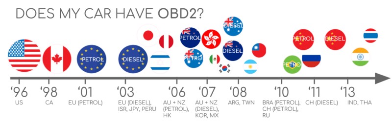
For most vehicles manufactured in recent decades, the answer is likely yes. OBD2 became mandatory in the United States for cars and light trucks in 1996, with similar mandates following in Europe and other regions. While the presence of a 16-pin OBD2 connector is a good indicator, it doesn’t guarantee full OBD2 compliance, especially in older models.
To determine if your vehicle is OBD2 compliant and likely utilizes the ISO CAN bus protocol:
- Manufacturing Year and Region:
- USA: Mandatory for cars/light trucks from 1996, medium-duty vehicles from 2005, and heavy-duty vehicles from 2010. ISO 15765-4 (CAN) became mandatory for US cars in 2008.
- Europe: Required for gasoline cars from 2001 and diesel cars (EOBD) from 2003.
- Vehicle Type: Almost all non-electric cars manufactured after these dates support OBD2 and predominantly use CAN bus.
Check your vehicle’s manufacturing year and region to determine OBD2 compliance.
A Brief History of OBD2 and the Rise of ISO CAN Bus
The origins of OBD2 trace back to California’s environmental regulations. The California Air Resources Board (CARB) mandated OBD systems in new cars from 1991 onwards for emission control. The Society of Automotive Engineers (SAE) played a pivotal role in standardizing OBD, leading to OBD2 with standardized DTCs and the universally adopted OBD connector (SAE J1962).
The rollout of OBD2 was a phased process:
- 1996: OBD2 mandated in the USA for cars and light trucks.
- 2001: OBD2 required in the EU for gasoline vehicles.
- 2003: OBD2 (EOBD) extended to diesel vehicles in the EU.
- 2005: OBD2 became mandatory for medium-duty vehicles in the US.
- 2008: ISO 15765-4 (CAN) mandated as the OBD2 communication protocol in US cars.
- 2010: OBD2 mandated for heavy-duty vehicles in the US.
OBD2 history is closely linked to emission control and evolving standards.
The timeline of OBD2 adoption reflects its increasing importance in vehicle diagnostics.
The future of OBD may involve remote diagnostics and integration with cloud and IoT technologies.
The shift to ISO 15765-4 CAN protocol as the backbone for OBD2 communication was driven by the need for a robust, high-speed, and standardized communication network within vehicles. CAN bus offered these advantages over earlier, slower protocols, enabling more comprehensive and faster data exchange for diagnostics and control.
The Future of OBD: OBD3, WWH-OBD, and the Role of ISO CAN Bus
OBD2 continues to evolve. While initially focused on emissions, its scope is expanding, and its implementation methods are becoming more sophisticated. Key trends shaping the future of OBD include:
- Electric Vehicles (EVs) and OBD: Interestingly, current regulations don’t mandate OBD2 for EVs. Consequently, many modern EVs don’t fully support standard OBD2 requests, often relying on OEM-specific protocols like UDS (Unified Diagnostic Services). However, reverse engineering efforts are making EV data accessible, as seen in case studies for Tesla, Hyundai/Kia, Nissan, and VW/Skoda.
- WWH-OBD and OBDonUDS: Recognizing the limitations of traditional OBD2 in data richness and protocol flexibility, newer standards like WWH-OBD (World Wide Harmonized OBD) and OBDonUDS (OBD on UDS) are emerging. These aim to enhance OBD communication by using UDS as the underlying protocol, offering greater data capacity and more advanced diagnostic capabilities, still often relying on ISO CAN bus for physical layer communication.
- OBD3 and Telematics: The concept of OBD3 envisions incorporating telematics into all vehicles for remote emissions monitoring. This could involve vehicles automatically transmitting VIN and DTCs via wireless communication to central servers, streamlining emission checks. While technologically feasible, it raises privacy concerns.
- OEM Control and Data Access: Automakers are increasingly interested in controlling access to vehicle data. Proposals to limit OBD2 functionality during driving and centralize data collection could impact third-party OBD2 service providers. Security concerns and the rise of ‘automotive big data’ are driving this shift, potentially disrupting the current OBD2 ecosystem.
Electric vehicles present a new frontier for OBD, with different approaches to data access.
Despite these potential shifts, ISO CAN bus protocol is likely to remain a critical communication layer in automotive diagnostics for the foreseeable future, even as higher-level protocols and data access paradigms evolve.
Deep Dive into OBD2 Standards and ISO 15765-4 CAN
OBD2 is a high-level protocol built upon lower-level communication methods. Think of OBD2 as the language and CAN bus as the communication channel. This is analogous to other CAN-based higher-layer protocols like J1939, CANopen, and NMEA 2000.
OBD2 standards, particularly when implemented over CAN bus, are defined by a set of SAE and ISO specifications, most notably ISO 15765. These standards cover various aspects, including:
- OBD2 Connector (SAE J1962 / ISO 15031-3): The physical interface for accessing vehicle data.
- Lower-Layer Protocols (ISO 15765-4): Specifies CAN bus as the primary physical and data link layer for OBD2 communication.
- OBD2 Parameter IDs (PIDs) (SAE J1979 / ISO 15031-5): Defines standardized codes for requesting specific vehicle parameters and diagnostic information.
The relationship between OBD2 and CAN bus, according to ISO standards, can be visualized using the 7-layer OSI model:
The OSI model illustrates how OBD2 and CAN bus standards interrelate.
As shown, SAE and ISO standards often overlap, reflecting the global harmonization efforts in automotive diagnostics. For instance, SAE J1979 and ISO 15031-5 are technically equivalent specifications for OBD2 diagnostic services, and SAE J1962 and ISO 15031-3 both define the OBD2 connector.
The OBD2 Connector: SAE J1962 and ISO 15031-3
The 16-pin OBD2 connector, standardized by SAE J1962 and ISO 15031-3, is the gateway to accessing vehicle data.
The standardized OBD2 connector pinout (Type A) is defined by SAE J1962.
Key features of the OBD2 connector include:
- Location: Typically found near the steering wheel, though its exact location can vary and may be hidden by a panel.
- Pin 16: Battery Power: Provides battery voltage, often even when the ignition is off, allowing diagnostic tools to operate.
- Pinout and Communication Protocol: The pinout configuration depends on the specific communication protocol used by the vehicle.
- Pins 6 & 14: CAN Bus (CAN-H & CAN-L): In CAN bus-based OBD2 systems, pins 6 and 14 are connected to the CAN high (CAN-H) and CAN low (CAN-L) lines, respectively, facilitating CAN communication.
OBD2 Connector Types: Type A vs. Type B
While Type A is most common in passenger cars, Type B OBD2 connectors are often found in medium and heavy-duty vehicles.
Type A and Type B OBD2 connectors differ primarily in voltage and physical keying.
The main differences between Type A and Type B connectors are:
- Voltage Supply: Type A typically provides 12V power, while Type B provides 24V, suitable for trucks and buses.
- Baud Rate: Cars (Type A) often use 500 kbps CAN baud rate, while heavy-duty vehicles (Type B) frequently use 250 kbps, with increasing adoption of 500 kbps.
- Physical Keying: Type B connectors have an interrupted groove, making them incompatible with Type A adapters, while Type B adapter cables are usually compatible with both Type A and Type B sockets.
Understanding these connector types is essential for selecting the correct OBD2 adapter and ensuring proper communication with the vehicle’s diagnostic system.
OBD2 Communication over CAN Bus: ISO 15765-4 in Detail
Since 2008, ISO 15765-4 (Diagnostics over CAN or DoCAN) has been the mandatory standard for OBD2 communication in US vehicles, solidifying ISO CAN bus protocol as the primary physical layer for OBD2.
ISO 15765-4 specifies a set of constraints and guidelines for implementing OBD2 diagnostics over CAN, focusing on the physical, data link, and network layers:
- CAN Bus Bit-rate: Must be either 250 kbps or 500 kbps.
- CAN IDs: Supports both 11-bit (standard) and 29-bit (extended) CAN identifiers.
- OBD Request/Response CAN IDs: Defines specific CAN IDs for OBD2 request and response messages.
- CAN Frame Data Length: Diagnostic CAN frames must have a data payload of 8 bytes.
- OBD2 Adapter Cable Length: Maximum length of 5 meters for the OBD2 adapter cable.
ISO 15765-4 standardizes OBD2 communication over CAN bus.
OBD2 CAN Identifiers: 11-bit and 29-bit
OBD2 communication over CAN relies on a request-response mechanism.
-
11-bit CAN Identifiers: Predominant in most cars.
- Functional Addressing Request ID:
0x7DF. This ID is used to broadcast a request to all OBD2-compliant ECUs, asking if they have data for the requested parameter. - Physical Addressing Request IDs:
0x7E0 - 0x7E7. Used for sending requests to specific ECUs (less common in general OBD2 requests). - Response IDs:
0x7E8 - 0x7EF. ECUs respond using these IDs.0x7E8is the most common response ID, typically from the Engine Control Module (ECM), and0x7E9often comes from the Transmission Control Module (TCM).
- Functional Addressing Request ID:
-
29-bit CAN Identifiers: Found in some vehicles, especially vans and medium/heavy-duty vehicles.
- Functional Addressing CAN ID:
0x18DB33F1. - Response IDs:
0x18DAF100to0x18DAF1FF(common responses are0x18DAF110and0x18DAF11E). These response IDs are sometimes represented in J1939 PGN format as PGN0xDA00(55808), which is reserved for ISO 15765-2 in the J1939-71 standard.
- Functional Addressing CAN ID:
OBD2 communication is based on request and response frames, identified by specific CAN IDs.
OBD2 vs. Proprietary CAN Protocols: Understanding the Difference
It’s crucial to understand that OBD2 is an overlay on top of the vehicle’s internal communication network. Vehicle ECUs primarily communicate using OEM-specific, proprietary CAN protocols for core vehicle functions. These protocols vary by manufacturer, model, and year, and are generally undocumented and require reverse engineering to understand.
When you connect an OBD2 scanner or CAN logger to the OBD2 port, you are typically interacting with the OBD2 protocol layer. While you might observe OEM-specific CAN data on the same bus, especially with basic CAN loggers, newer vehicles often implement a gateway that filters CAN traffic on the OBD2 port, allowing only OBD2 communication.
OBD2 is a standardized protocol that coexists with OEM-specific proprietary CAN protocols within the vehicle.
Think of OBD2 as a standardized “diagnostic language” spoken in parallel to the OEM’s “native language” used for vehicle control and operation.
Bit-rate and CAN ID Validation: Ensuring Proper Communication
Given the variations in bit-rates (250 kbps or 500 kbps) and CAN ID lengths (11-bit or 29-bit), diagnostic tools need to validate these parameters for successful OBD2 communication. ISO 15765-4 provides a recommended initialization sequence to determine the correct combination.
The validation process relies on the fact that OBD2-compliant vehicles must respond to a mandatory OBD2 request (Service 0x01 PID 0x00). By sending test requests at different bit-rates and monitoring for responses (or CAN error frames indicating incorrect bit-rate), a tool can automatically detect the correct communication parameters.
Flowchart illustrating the process of validating bit-rate and CAN ID settings for OBD2 communication.
Modern ISO 15765-4 versions also account for OBDonUDS implementations. Tools may send additional UDS requests (Service 0x22, DID 0xF810) to test for OBDonUDS support.
While OBDonUDS and WWH-OBD are gaining traction, especially in commercial vehicles, OBDonEDS (OBD2, SAE OBD, EOBD, ISO OBD) remains the prevalent standard in most non-EV passenger vehicles today.
While CAN (ISO 15765) dominates, older OBD2 implementations used other lower-layer protocols.
Beyond CAN: Legacy OBD2 Protocols
While ISO 15765 (CAN bus) is the dominant lower-layer protocol for OBD2 today, especially in vehicles manufactured post-2008, older vehicles may utilize one of these four legacy protocols:
- ISO 14230-4 (KWP2000): Keyword Protocol 2000, common in 2003+ Asian vehicles.
- ISO 9141-2: Used in European, Chrysler, and Asian vehicles (2000-2004).
- SAE J1850 VPW (Variable Pulse Width Modulation): Primarily in older GM vehicles.
- SAE J1850 PWM (Pulse Width Modulation): Primarily in older Ford vehicles.
Understanding these legacy protocols can be helpful when working with older vehicles, although CAN bus (ISO 15765) is the primary focus for modern OBD2 diagnostics and the Obd2 Iso Canbus Protocol keyword.
ISO-TP: Transporting OBD2 Messages over CAN (ISO 15765-2)
OBD2 data transmitted over CAN bus often utilizes ISO-TP (ISO 15765-2), a transport protocol that enables sending data payloads larger than the 8-byte CAN frame limit. This is essential for OBD2 functions that require transmitting more data, such as retrieving the Vehicle Identification Number (VIN) or Diagnostic Trouble Codes (DTCs).
ISO-TP handles segmentation (splitting large messages into smaller CAN frames), flow control (managing data transmission rate), and reassembly (reconstructing the original message from segmented frames). For simpler OBD2 requests and responses where data fits within a single CAN frame, ISO-TP defines the use of “Single Frame” (SF) messages. In SF messages, the first byte (PCI field) indicates the payload length, leaving 7 bytes for OBD2-specific data.
ISO-TP defines different frame types for transporting OBD2 messages, including Single Frame and multi-frame communication.
Decoding the OBD2 Diagnostic Message: SAE J1979 and ISO 15031-5
To understand OBD2 communication at the message level, consider the structure of a “Single Frame” OBD2 CAN message. It consists of:
- CAN Identifier: (e.g., 0x7DF for functional request, 0x7E8 for response)
- Data Length (PCI Field): First byte of the CAN data payload, indicating the length of the OBD2 data.
- OBD2 Data: Contains:
- Mode (Service): Defines the type of diagnostic service being requested (e.g., real-time data, DTCs).
- Parameter ID (PID): Specifies the particular parameter being requested within a given mode (e.g., vehicle speed, engine RPM).
- Data Bytes: Contains the actual parameter value or diagnostic information.
Breakdown of an OBD2 message structure, showing Mode, PID, and data bytes.
Example: Requesting and Receiving Vehicle Speed (PID 0x0D)
Let’s illustrate with a practical example: requesting vehicle speed.
- Request: A diagnostic tool sends a CAN message with:
- CAN ID:
0x7DF(functional request) - Payload:
02 01 0D(PCI field 0x02, Mode 0x01, PID 0x0D)
- CAN ID:
- Response: The vehicle responds with a CAN message:
- CAN ID:
0x7E8(response from ECM) - Payload:
03 41 0D 32(PCI field 0x03, Mode response 0x41 [0x01+0x40], PID 0x0D, Speed value 0x32)
- CAN ID:
The vehicle speed value 0x32 (hexadecimal) translates to 50 in decimal. Consulting the OBD2 PID documentation for PID 0x0D reveals that the unit is km/h. Thus, the vehicle is reporting a speed of 50 km/h.
Example of OBD2 request and response frames for vehicle speed (PID 0x0D).
Decoding PID 0x0D (Vehicle Speed) involves understanding the scaling and units defined in the OBD2 standard.
OBD2 Services (Modes): The 10 Diagnostic Functions
OBD2 defines 10 standard diagnostic services, often referred to as “modes,” each serving a specific purpose:
The 10 standardized OBD2 services (modes) provide access to different types of diagnostic information.
- Mode 0x01: Show current data: Retrieves real-time sensor data and vehicle parameters.
- Mode 0x02: Show freeze frame data: Displays data captured when a DTC was set.
- Mode 0x03: Show stored DTCs: Reads currently active Diagnostic Trouble Codes.
- Mode 0x04: Clear DTCs and stored values: Resets DTCs and clears related data.
- Mode 0x05: Oxygen sensor monitoring test results: Retrieves results from oxygen sensor tests.
- Mode 0x06: On-board monitoring test results for non-continuously monitored systems: Accesses test results for specific systems.
- Mode 0x07: Show pending DTCs: Displays DTCs that haven’t yet triggered the MIL.
- Mode 0x08: Control operation of on-board system, test or component: Allows control of certain vehicle systems for testing.
- Mode 0x09: Request vehicle information: Retrieves vehicle-specific information like VIN and calibration IDs.
- Mode 0x0A: Show permanent DTCs: Reads DTCs that cannot be cleared by normal means.
Vehicles are not required to support all 10 modes, and manufacturers may implement additional OEM-specific modes beyond the standard set. In OBD2 messages, the mode is the second byte in the data payload. In a request, the mode is directly specified (e.g., 0x01). In a response, 0x40 is added to the requested mode value (e.g., a response to mode 0x01 will start with mode value 0x41).
OBD2 Parameter IDs (PIDs): Accessing Specific Data Points
Within each OBD2 mode, Parameter IDs (PIDs) are used to request specific data points. Mode 0x01 (Show current data), for example, includes approximately 200 standardized PIDs covering parameters like speed, RPM, engine temperature, and fuel level. However, vehicles typically support only a subset of these PIDs.
A crucial PID for OBD2 compatibility testing is PID 0x00 in Mode 0x01. If an ECU supports any OBD2 services, it must support Mode 0x01 PID 0x00. Responding to this PID, the ECU indicates which PIDs in the range 0x01-0x20 it supports. Similarly, PIDs 0x20, 0x40, 0x60, etc., are used to determine support for subsequent PID ranges within Mode 0x01.
PIDs are used within OBD2 modes to specify the exact parameter being requested.
Online OBD2 PID overview tools can help in understanding and utilizing different PIDs.
OBD2 PID Overview Tools: Your Diagnostic Resource
SAE J1979 and ISO 15031-5 appendices detail the scaling and decoding information for standard OBD2 PIDs, enabling conversion of raw data bytes into meaningful physical values.
For quick PID lookups and request frame construction, online OBD2 PID overview tools are invaluable resources. These tools often provide interactive interfaces for exploring PIDs and understanding their data formats.
OBD2 PID overview tool
Utilize OBD2 PID overview tools to simplify PID lookup and data decoding.
Practical Guide: Logging and Decoding OBD2 Data with ISO CAN Bus Protocol
Let’s explore a practical example of logging OBD2 data using a CAN bus data logger like the CANedge, demonstrating how to interact with the obd2 iso canbus protocol.
The CANedge allows configuration of custom CAN frames for transmission, making it suitable for sending OBD2 requests. Connected to a vehicle via an OBD2-DB9 adapter cable, it can log OBD2 responses.
A CAN bus data logger can be configured to send OBD2 requests and record responses.
Analyzing responses to ‘Supported PIDs’ requests helps identify vehicle-specific OBD2 capabilities.
Step 1: Bit-rate, ID, and Supported PID Validation
Following ISO 15765-4 recommendations, begin by validating communication parameters and identifying supported PIDs:
- Bit-rate Test: Send a CAN frame at 500 kbps and check for successful transmission. If unsuccessful, try 250 kbps.
- Bit-rate Confirmation: Use the identified bit-rate for all subsequent communication.
- Supported PIDs Request: Send “Supported PIDs” requests (Mode 0x01, PID 0x00, and subsequent range PIDs like 0x20, 0x40, etc.).
- Response Analysis: Review responses to determine CAN ID type (11-bit or 29-bit) and supported PIDs based on response data.
Pre-configured settings can streamline these initial tests. Most post-2008 non-EV vehicles commonly support 40-80 PIDs using 500 kbps, 11-bit CAN IDs, and the OB