Disclaimer: I am not an expert or a professional mechanic. This guide is based on my personal experience, and while it worked for me, following these steps is at your own risk. I am not responsible for any damage or issues that may arise from attempting this DIY project, including but not limited to equipment malfunction, ECU damage, or unforeseen consequences.
Creating a custom OBD2 connector can be useful in various situations, especially when dealing with vehicles that may not have a standard OBD2 port or when you need a specific connection for diagnostic tools. This guide will walk you through the process of wiring your own OBD2 connector using a few readily available tools and parts, focusing on the essential Obd2 Pin connections needed for basic diagnostic functions.
Tools and Parts You’ll Need
Before starting, gather these tools and parts to ensure a smooth process:
- Wire strippers/cutters: For preparing the wires.
- Needle-nose pliers: Helpful for handling small components and crimping.
- Molex crimping tool (optional but recommended): For secure pin crimping.
- Soldering iron (recommended): To enhance wire connection strength.
- 4-pin connector: (Corsa Technic – 4-Pin Connector; pin/wire size = 22-16AWG; insulation/seal size = 1.3-1.7mm)
- OBD-II Cable: (Corsa Technic – OBD-II Cable)
If you prefer to source your own wires, you can purchase a female OBD-II connector separately and use your existing wires to connect the OBD-II and 4-pin connectors. Ensure you select a 4-pin connector compatible with your wire size.
Step-by-Step Guide to Wiring Your OBD2 Connector Pins
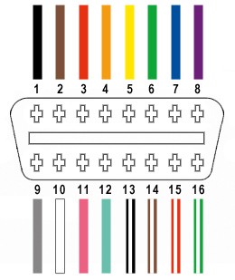
For this custom connector, we will utilize only four essential obd2 pin connections from the OBD-II connector. These pins are crucial for basic diagnostic communication:
- Pin 4: Chassis ground (typically an orange wire on the OBD2 cable)
- Pin 6: CAN (J-2234) High (typically a green wire on the OBD2 cable)
- Pin 14: CAN (J-2234) Low (typically a brown wire with a white stripe on the OBD2 cable)
- Pin 16: Battery power (typically a green wire with a white stripe on the OBD2 cable)
Step 1: Prepare the OBD2 Cable Wires
Start by preparing the OBD-II cable. If your cable has an outer sheath and shielding, carefully remove them to access the individual wires. Identify and separate the four wires corresponding to obd2 pin 4, 6, 14, and 16 as listed above. Secure the remaining unused wires to keep them organized and out of the way – zip ties can be helpful for this.
Step 2: Prepare the 4-Pin Connector Pins
The wires in the OBD-II cable might be thinner (26AWG) than ideal for the 4-pin connector pins (designed for 22AWG). To compensate for this difference, carefully strip about 3/8″ of insulation from the ends of the four selected wires. Fold the exposed wire strands over and twist them to increase the wire thickness, making them fit better within the 4-pin connector pins. Slide a rubber seal (included with the 4-pin connector kit) onto each of the prepared wires.
Step 3: Connect and Secure the Wires to the Pins (Soldering/Crimping)
The pins for the 4-pin connector have two sets of prongs. The front prongs are designed to clamp onto the wire, and the rear prongs secure the rubber seal. Insert a prepared wire into a pin, ensuring the exposed wire aligns with the front prongs.
Soldering is highly recommended for a robust and reliable connection, especially with thinner wires. Solder the wire to the pin connector for a solid electrical and mechanical bond. If you choose not to solder and have a Molex crimping tool, use it to crimp the front prongs securely around the wire. If you don’t have a crimping tool, needle-nose pliers can be used carefully to fold the prongs over the wire. Ensure a tight crimp to establish good contact.
Step 4: Secure the Rubber Seals
Slide the rubber seal up the wire until it sits between the rear prongs of the pin. Use the same crimping technique (crimping tool or needle-nose pliers) to fold these rear prongs over the rubber seal. This provides strain relief and environmental protection to the connection.
Step 5: Wiring Diagram and Pin Orientation (Crucial OBD2 Pin Information)
While not definitively proven necessary, it is often recommended to twist pairs of wires in similar DIY guides. Pair and twist the wires as follows:
- Pin 4 (orange) / Pin 16 (green w/white stripe)
- Pin 6 (green) / Pin 14 (brown w/white stripe)
Step 6: Assemble the 4-Pin Connector
Insert the pins into the 4-pin connector housing in the correct orientation. Refer to the diagram below for proper obd2 pin placement within the connector:
- Pin 14 (brown w/white stripe) > Connector slot A
- Pin 6 (green) > Connector slot B
- Pin 16 (green w/white stripe) > Connector slot C
- Pin 4 (orange) > Connector slot D
Push each pin into the rear of the connector until you hear a click, indicating it is locked securely in place. Using needle-nose pliers can aid in gently pulling the wire from the front to ensure the pin is fully seated and locked.
Step 7: Final Assembly and Testing
With all pins correctly inserted and locked, your custom OBD2 connector is complete!
Test your new connector to ensure it functions as expected. In a successful test, this custom connector was used to check and clear a self-induced error code.
If any step is unclear, or if you encounter issues, revisit the steps and double-check your obd2 pin connections. If you have further questions, feel free to ask for clarification or more detailed explanations.