Modern vehicles rely heavily on their onboard diagnostic (OBD2) systems for monitoring and maintaining optimal performance. The OBD2 port, a standardized interface, allows mechanics and vehicle owners to access this system using diagnostic tools. A crucial component of this system is the OBD2 plug, which can sometimes encounter issues. This article delves into the Obd2 Plug Diagram, common problems, and a straightforward DIY solution, drawing from real-world experiences in automotive repair.
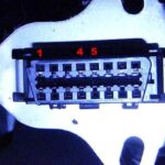
The OBD2 port is typically located within easy reach of the driver, often under the dashboard. It serves as the gateway to your vehicle’s computer, providing access to a wealth of data related to engine performance, emissions, and various other systems. Understanding the OBD2 plug diagram is essential for anyone looking to diagnose car problems themselves or perform even basic repairs. The diagram outlines the pinout of the 16-pin connector, assigning specific functions to each pin, such as power, ground, communication protocols (like CAN bus, ISO 9141-2, and J1850), and manufacturer-specific uses.
One common issue vehicle owners face is damage to the OBD2 plug itself. This can occur due to accidental kicks, impacts, or simply wear and tear over time. A damaged OBD2 plug can prevent proper communication with diagnostic scanners, making it impossible to read error codes or perform necessary diagnostics. Symptoms of a faulty OBD2 plug can range from intermittent scanner connection issues to a complete inability to establish a link with the vehicle’s computer.
[alt]: A close-up view of a typical 16-pin OBD2 connector, highlighting the pin layout and numbering for diagnostic purposes.
Fortunately, repairing a damaged OBD2 plug can often be a DIY-friendly task, as demonstrated by a user’s experience with a Dodge Durango. In a recent forum post, a Durango owner described resolving an OBD2 issue by sourcing a replacement plug from a salvage yard. The user acquired a used OBD2 plug for a minimal cost and performed a simple “butt connection” to splice the new plug into the existing wiring harness. This straightforward fix effectively resolved their diagnostic communication problems, highlighting the potential for cost-effective DIY repairs in such situations.
This type of repair underscores the value of understanding basic automotive electrical systems and the accessibility of replacement parts. While a complete OBD2 plug diagram might seem complex at first glance, numerous online resources and repair manuals provide detailed pinout information. Armed with a diagram and basic wiring knowledge, many car owners can confidently tackle OBD2 plug replacements and similar electrical repairs.
For those considering a DIY fix, it’s crucial to:
- Identify the correct OBD2 plug diagram for your vehicle: Pin assignments can vary slightly between manufacturers and models, although the standard 16-pin layout is consistent.
- Carefully disconnect the vehicle’s battery: This is a fundamental safety precaution when working with automotive electrical systems.
- Use appropriate wiring techniques: Butt connectors, soldering, and proper insulation are essential for a reliable and safe repair.
- Double-check all connections: Refer to the OBD2 plug diagram to ensure each wire is connected to the correct pin on the replacement plug.
[alt]: Illustration depicting the process of using butt connectors to join wires for an OBD2 plug repair, emphasizing proper insulation and secure connections.
While the Durango owner’s experience highlights a successful DIY repair, it’s important to acknowledge that more complex OBD2 system issues may require professional diagnosis and repair. However, for common problems like a physically damaged plug, understanding the OBD2 plug diagram and embracing a DIY approach can save time and money, getting you back on the road quickly. Always consult reliable repair resources and prioritize safety when working on your vehicle’s electrical systems.