Looking for an in-depth understanding of OBD2 specifications?
This guide provides a comprehensive overview of the On-Board Diagnostic (OBD2) protocol, focusing on the essential specifications you need to know. We delve into the OBD2 connector, OBD2 Parameter IDs (PIDs), communication protocols including CAN bus, and where to find detailed Obd2 Specification Pdfs.
As a car repair expert at obd-de.com, I’ve compiled this resource to be your go-to guide for mastering OBD2. Whether you’re a mechanic, engineer, or car enthusiast, this article will enhance your knowledge of vehicle diagnostics.
This is your expert guide to understanding OBD2 specifications.
You can also explore our OBD2 introductory video or download our comprehensive CAN bus guide in PDF format for further reading.
Understanding OBD2 Specifications
Author: Martin Falch (Expert in Automotive Diagnostics) (Updated January 2025)
Download CAN Bus Guide as PDF
What is OBD2? Delving into the Specifications
OBD2 is a standardized on-board diagnostic system in vehicles, designed to monitor and report on vehicle health. The OBD2 specification standardizes how diagnostic trouble codes (DTCs) and real-time data are accessed via the OBD2 connector. The core of the OBD2 specification lies in its ability to provide consistent diagnostic information across different vehicle makes and models.
You’re likely already familiar with OBD2 in some form:
The check engine light on your dashboard is part of the OBD2 system. It signals a detected issue, prompting a diagnostic check. Mechanics use OBD2 scanners, tools designed according to OBD2 specifications, to read and interpret this data.
Connecting an OBD2 reader to the 16-pin OBD2 connector, typically located near the steering wheel, allows communication with the vehicle’s computer. The scanner sends ‘OBD2 requests’ as defined by the OBD2 specification, and the car responds with ‘OBD2 responses’. These responses contain data like speed, engine temperature, fuel levels, and DTCs – all structured by the OBD2 specification – enabling efficient troubleshooting.
Image showing a malfunction indicator light (MIL) and an OBD2 scan tool, illustrating the practical application of OBD2 diagnostics.
OBD2 Compatibility: Specification Rollout
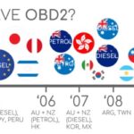
Is your car OBD2 compliant? Almost certainly, if it’s a newer, non-electric vehicle. OBD2 compliance is mandated for most modern cars, and many utilize CAN bus as their communication network. However, older vehicles with a 16-pin connector may not fully adhere to the OBD2 specification. The vehicle’s origin and purchase date are key indicators of OBD2 compliance:
Infographic detailing OBD2 compliance timelines for different regions (EU, US) and vehicle types, helping users determine if their car is OBD2 compliant based on purchase location and date.
OBD2 History: Evolution of the Specification
OBD2’s origins trace back to California, where the California Air Resources Board (CARB) mandated OBD for all new vehicles from 1991 onwards for emissions monitoring. This initial requirement laid the groundwork for the standardized OBD2 specification we know today.
The Society of Automotive Engineers (SAE) played a crucial role in developing the OBD2 standard, focusing on standardizing DTCs and the physical OBD connector. SAE J1962 is the specification defining the OBD connector.
The OBD2 specification rollout was gradual but comprehensive:
- 1996: OBD2 became mandatory in the USA for cars and light trucks.
- 2001: The EU mandated OBD2 for gasoline cars.
- 2003: EU extended the mandate to diesel cars (EOBD).
- 2005: OBD2 was required in the US for medium-duty vehicles.
- 2008: US vehicles were required to use ISO 15765-4 (CAN) as the foundation for OBD2 communication, solidifying CAN bus within the OBD2 specification.
- 2010: OBD2 mandate extended to heavy-duty vehicles in the US.
Visual representation of OBD2 history, emphasizing its evolution from emission control to a broader diagnostic standard.
Timeline graphic illustrating the key milestones in OBD2 history and its standardization across different regions and vehicle types.
Conceptual image representing the future trends in OBD, including remote diagnostics, cloud connectivity, and potential OBD3 developments.
OBD2 Future: Trends and Specification Evolution
OBD2 remains fundamental, but its future is evolving.
Originally designed for emissions control, legislated OBD2 requirements do not extend to electric vehicles. Consequently, most modern EVs do not support standard OBD2 requests, opting instead for OEM-specific UDS communication. This makes accessing EV data challenging without reverse engineering efforts, as seen in case studies for Tesla, Hyundai/Kia, Nissan and VW/Skoda EVs.
Current OBD2 implementations face limitations in data richness and lower-layer protocols. Modern alternatives like WWH-OBD (World Wide Harmonized OBD) and OBDonUDS (OBD on UDS) are emerging. These aim to improve OBD communication using the UDS protocol. Learn more in our UDS protocol introduction.
Connected cars are pushing OBD2 towards remote diagnostics. Manual emission checks are inefficient. OBD3, envisioning telematics integration, proposes adding radio transponders to vehicles. This would allow vehicle identification number (VIN) and DTC transmission via WiFi to central servers for automated monitoring.
Devices like the CANedge2 WiFi CAN logger and CANedge3 3G/4G CAN logger already enable CAN/OBD2 data transfer via WiFi/cellular. While convenient and cost-saving, this raises privacy concerns.
While OBD2 was intended for repair shop diagnostics, third-party use for real-time data via OBD2 dongles, CAN loggers etc., is widespread. However, the German car industry seeks to limit this, as stated by Christoph Grote, SVP Electronics, BMW (2017):
“OBD has been designed to service cars in repair shops. In no way has it been intended to allow third parties to build a form of data-driven economy on the access through this interface“
The proposal is to disable OBD2 functionality during driving, centralizing data collection with manufacturers, controlling ‘automotive big data’. Arguments cite security benefits (reducing car hacking risks), but many see commercial motivations. The future impact on the third-party OBD2 service market remains uncertain.
Image depicting an OBD2 connector being removed from an electric vehicle, symbolizing the trend of EVs moving away from standard OBD2 implementations and towards proprietary systems.
Enhance Your OBD2 Expertise: Download our CAN Bus Guide PDF
Want to master CAN bus and OBD2 specifications?
Our ‘Ultimate CAN Guide’ provides 12 in-depth introductions in a comprehensive 160+ page PDF:
Download CAN Bus Guide Now
OBD2 Standards: Defining the Specification
On-board diagnostics, OBD2, is a higher-layer protocol, a ‘language’ built upon communication methods like CAN. OBD2 shares similarities with other CAN-based protocols like J1939, CANopen and NMEA 2000.
OBD2 standards comprehensively specify the OBD2 connector, lower-layer protocols, OBD2 Parameter IDs (PIDs), and more. These specifications are detailed in various publicly available OBD2 specification PDFs from organizations like SAE and ISO.
The standards can be viewed through a 7-layer OSI model. Notably, both SAE and ISO standards cover multiple layers, reflecting US (SAE) and EU (ISO) OBD definitions. Many standards are technically equivalent, such as SAE J1979 vs. ISO 15031-5 and SAE J1962 vs. ISO 15031-3. For precise technical details, referring to the official OBD2 specification PDF documents is recommended.
OSI model diagram illustrating the layers relevant to OBD2 and CAN bus, highlighting the standards (ISO, SAE) at each layer and the relationship between OBD2 and CAN bus protocols.
Diagram of an OBD2 connector pinout (Type A, female socket), detailing the function of each pin in accordance with OBD2 specifications.
The OBD2 Connector [SAE J1962 Specification]
The 16-pin OBD2 connector, detailed in the SAE J1962 specification / ISO 15031-3 (obtainable as an OBD2 specification PDF), provides easy vehicle data access. SAE J1962 is a key document when seeking the OBD2 connector specification pdf.
The illustration shows a Type A OBD2 pin connector (Data Link Connector, DLC).
Key aspects of the OBD2 connector specification:
- Location: Usually near the steering wheel, potentially hidden.
- Pin 16: Battery power supply (often active even when ignition is off).
- Pinout: Varies based on communication protocol. Refer to the OBD2 specification PDF for detailed pinout diagrams for different protocols.
- Common Protocol: CAN bus is prevalent, typically connected to pins 6 (CAN-H) and 14 (CAN-L).
OBD2 Connector Types: A vs. B [SAE J1962 Specification]
You may encounter Type A and Type B OBD2 connectors, both defined in the SAE J1962 specification. Type A is common in cars, while Type B is often found in medium and heavy-duty vehicles. The OBD2 specification pdf SAE J1962 details both connector types.
Both types have similar pinouts but differ in power supply outputs (12V for Type A, 24V for Type B) and often baud rates (cars typically 500K, heavy-duty vehicles often 250K, sometimes 500K).
Type B connectors have an interrupted groove in the middle, distinguishing them physically. Type B OBD2 adapter cables are compatible with both Type A and B sockets, while Type A adapters fit only Type A sockets. Consulting the OBD2 specification pdf can clarify compatibility.
Diagram contrasting OBD2 Connector Type A and Type B, highlighting differences in power supply, typical vehicle applications, and physical characteristics as outlined in the SAE J1962 OBD2 connector specification pdf.
Diagram illustrating the relationship between OBD2 and CAN bus within the ISO 15765 framework, emphasizing CAN bus as a lower-layer protocol for OBD2 communication.
OBD2 and CAN bus [ISO 15765-4 Specification]
Since 2008, CAN bus is the mandatory lower-layer protocol for OBD2 in US vehicles, according to the ISO 15765 specification. ISO 15765-4, often referred to as Diagnostics over CAN or DoCAN, is a crucial OBD2 specification pdf to understand for CAN-based OBD2 systems.
ISO 15765-4 (Diagnostics on Controller Area Network – Part 4: Requirements on emissions-related systems) defines constraints on the CAN standard (ISO 11898) for OBD2.
It standardizes the CAN interface for diagnostic equipment, focusing on physical, data link, and network layers:
- CAN bus bit-rate: 250K or 500K. The OBD2 specification pdf details these bit-rate options.
- CAN IDs: 11-bit or 29-bit. Both standard and extended CAN IDs are permitted under the OBD2 specification pdf.
- Specific CAN IDs: Defined for OBD requests/responses within the OBD2 specification pdf.
- Diagnostic CAN frame data length: 8 bytes. The OBD2 specification pdf mandates this frame size for diagnostic messages.
- OBD2 adapter cable: Max 5 meters. Cable length is also specified to ensure signal integrity, as per the OBD2 specification pdf.
OBD2 CAN Identifiers (11-bit, 29-bit) [ISO 15765-4 Specification]
OBD2 communication uses request/response messages. The OBD2 specification pdf ISO 15765-4 details CAN ID usage.
Most cars use 11-bit CAN IDs for OBD2. ‘Functional Addressing’ ID 0x7DF broadcasts requests to all OBD2-compatible ECUs (ISO 15765-4). ‘Physical Addressing’ requests to specific ECUs (0x7E0-0x7E7) are less common.
ECU responses use 11-bit IDs 0x7E8-0x7EF. 0x7E8 (ECM – Engine Control Module) and 0x7E9 (TCM – Transmission Control Module) are common response IDs.
Some vehicles (vans, light/medium/heavy-duty) use 29-bit CAN identifiers for OBD2.
29-bit ‘Functional Addressing’ CAN ID is 0x18DB33F1.
Responses use CAN IDs 0x18DAF100 to 0x18DAF1FF (typically 18DAF110 and 18DAF11E). Response ID is sometimes shown as J1939 PGN 0xDA00 (55808), marked as ‘Reserved for ISO 15765-2’ in J1939-71. Refer to the OBD2 specification pdf for comprehensive details on CAN ID allocation.
Diagram illustrating the OBD2 request-response message flow, highlighting the role of PIDs and data parameters in diagnostic communication.
Conceptual diagram contrasting OBD2 standard CAN bus communication with proprietary OEM-specific CAN protocols, emphasizing that OBD2 is an additional diagnostic layer.
OBD2 vs. Proprietary CAN Protocols
Vehicle ECUs operate using OEM-proprietary CAN protocols, not OBD2. These protocols are vehicle brand, model, and year-specific. Interpreting this OEM data is typically impossible without reverse engineering.
Connecting a CAN bus data logger to the OBD2 connector may capture OEM-specific CAN data (1000-2000 frames/second). However, newer cars often use a gateway to block OEM data access via the OBD2 port, allowing only OBD2 communication.
OBD2 is an ‘extra’ higher-layer protocol alongside OEM-specific protocols. The OBD2 specification pdf focuses on this diagnostic layer, not the underlying OEM protocols.
Bit-rate and ID Validation [ISO 15765-4 Specification]
OBD2 can use two bit-rates (250K, 500K) and two CAN ID lengths (11-bit, 29-bit), resulting in 4 combinations. Modern cars commonly use 500K and 11-bit IDs. Diagnostic tools should systematically verify these parameters, following procedures detailed in the OBD2 specification pdf ISO 15765-4.
ISO 15765-4 provides initialization sequences to determine the correct combination. This leverages the requirement that OBD2-compliant vehicles must respond to a mandatory OBD2 request (see OBD2 PID section) and that incorrect bit-rates cause CAN error frames.
Newer ISO 15765-4 versions account for OBDonUDS vs. OBDonEDS. This article focuses on OBD2/OBDonEDS (ISO 15031-5/SAE J1979) vs. WWH-OBD/OBDonUDS (ISO 14229, ISO 27145-3/SAE J1979-2).
To test for OBDonEDS vs. OBDonUDS, tools may send UDS requests (service 0x22, DID 0xF810 – protocol identification) with 11-bit/29-bit functional address IDs. OBDonUDS-supporting vehicles must respond to this DID.
OBDonEDS (OBD2, SAE OBD, EOBD, ISO OBD) is common in non-EV cars. WWH-OBD is primarily used in EU trucks/buses. The OBD2 specification pdf documents differentiate between these OBD variants.
Flowchart illustrating the OBD2 bit-rate and CAN ID validation process according to ISO 15765-4, guiding diagnostic tools in automatically detecting the correct communication parameters.
Diagram outlining the five lower-layer OBD2 protocols (CAN/ISO 15765, KWP2000/ISO14230-4, ISO 9141-2, SAE J1850 VPW, SAE J1850 PWM), showcasing the evolution of OBD2 communication standards.
Five Lower-Layer OBD2 Protocols
CAN (ISO 15765) is now the dominant lower-layer OBD2 protocol. However, older vehicles (pre-2008) may use other protocols. Pinouts can help identify the protocol used. These legacy protocols are also detailed in older OBD2 specification pdf documents.
- ISO 15765 (CAN bus): Mandatory in US cars since 2008, now widely used.
- ISO14230-4 (KWP2000): Keyword Protocol 2000, common in 2003+ Asian cars.
- ISO 9141-2: Used in EU, Chrysler & Asian cars (2000-04).
- SAE J1850 (VPW): Mostly in older GM cars.
- SAE J1850 (PWM): Mostly in older Ford cars.
Transporting OBD2 Messages via ISO-TP [ISO 15765-2 Specification]
OBD2 data is transported on CAN bus via ISO-TP (ISO 15765-2), a transport protocol enabling payloads exceeding 8 bytes. ISO 15765-2, the OBD2 transport protocol specification pdf, is essential for understanding multi-frame OBD2 communication. This is needed for VIN and DTC extraction. ISO 15765-2 handles segmentation, flow control, and reassembly. See our UDS introduction for details.
Often, OBD2 data fits within a single CAN frame. ISO 15765-2 specifies ‘Single Frame’ (SF) usage. The 1st data byte (PCI field) contains payload length (excluding padding), leaving 7 bytes for OBD2 communication. The OBD2 specification pdf details frame formats.
Diagram illustrating the different ISO-TP frame types (Single Frame, First Frame, Consecutive Frame, Flow Control Frame) used for OBD2 communication, as specified in ISO 15765-2 OBD2 specification pdf.
The OBD2 Diagnostic Message [SAE J1979, ISO 15031-5 Specifications]
To understand OBD2 on CAN, consider a ‘Single Frame’ OBD2 CAN message. An OBD2 message consists of an identifier, data length (PCI field), and data (Mode, PID, data bytes). SAE J1979 and ISO 15031-5, the OBD2 diagnostic message specification pdf documents, define the structure and content of these messages.
Breakdown of an OBD2 message structure, illustrating the positions of Mode, PID (Parameter ID), and data bytes within the CAN frame payload, according to OBD2 message specifications.
Example: OBD2 Request/Response
Consider a ‘Vehicle Speed’ parameter request/response example.
A tool sends a request to the car (CAN ID 0x7DF) with 2 payload bytes: Mode 0x01 and PID 0x0D. The car responds (CAN ID 0x7E8) with 3 payload bytes, including speed value in the 4th byte, 0x32 (decimal 50).
OBD2 PID 0x0D decoding rules indicate a physical value of 50 km/h. These decoding rules are found in the OBD2 specification pdf.
Next, we’ll explore OBD2 modes and PIDs.
Example of an OBD2 request (CAN ID 7DF) and response (CAN ID 7E8) for Vehicle Speed, illustrating the message exchange for retrieving a specific PID value.
Detailed example of OBD2 PID 0x0D (Vehicle Speed), showing the request and response frames with data bytes and the conversion to a physical value (km/h), according to OBD2 PID specifications.
Diagram outlining the 10 OBD2 service modes (or modes), including functions like showing current data, freeze frame data, and clearing DTCs, as defined in OBD2 service mode specifications.
The 10 OBD2 Services (Modes) [SAE J1979, ISO 15031-5 Specifications]
There are 10 standardized OBD2 diagnostic services (modes). Mode 0x01 shows real-time data; others handle DTCs or freeze frame data. The OBD2 specification pdf SAE J1979 and ISO 15031-5 detail these modes.
Vehicles may not support all OBD2 modes and might include OEM-specific modes beyond the 10 standard ones.
In OBD2 messages, mode is the 2nd byte. In requests, mode is direct (e.g., 0x01). In responses, 0x40 is added to the mode (e.g., 0x41). The OBD2 specification pdf clarifies mode encoding.
OBD2 Parameter IDs (PIDs) [SAE J1979, ISO 15031-5 Specifications]
Each OBD2 mode contains Parameter IDs (PIDs). Mode 0x01 has ~200 standardized PIDs for real-time data like speed, RPM, and fuel level. However, vehicles support only a subset of PIDs in each mode. The OBD2 specification pdf lists all standardized PIDs.
PID 0x00 in mode 0x01 is special. If an emissions-related ECU supports any OBD2 services, it must support mode 0x01 PID 0x00. Responding to PID 0x00, the ECU indicates support for PIDs 0x01-0x20. PID 0x00 is a fundamental ‘OBD2 compatibility test’. PIDs 0x20, 0x40, …, 0xC0 indicate support for remaining mode 0x01 PIDs. The OBD2 specification pdf details PID 0x00 functionality.
Diagram reiterating the OBD2 request-response process, focusing on the role of PID in specifying the requested parameter and the data parameters in the response.
Screenshot of an OBD2 PID overview tool, demonstrating a practical resource for exploring and understanding available OBD2 PIDs within service 0x01, complementing the information found in OBD2 specification PDFs.
Tip: OBD2 PID Overview Tool
SAE J1979 and ISO 15031-5 appendices provide scaling information for standard OBD2 PIDs for data decoding. These details are also often summarized in OBD2 specification PDF summaries.
Our OBD2 PID overview tool helps construct OBD2 requests and dynamically decode responses for mode 0x01 PIDs.
OBD2 PID overview tool
How to Log and Decode OBD2 Data
This section demonstrates OBD2 data logging with the CANedge CAN bus data logger.
CANedge allows custom CAN frame transmission, enabling OBD2 logging.
Connect CANedge to your vehicle using our OBD2-DB9 adapter cable.
Diagram illustrating the setup for OBD2 data logging, showing the CANedge data logger connected to a vehicle’s OBD2 port and sending PID requests.
Validating bit-rate for OBD2 communication.
Reviewing ‘Supported PIDs’ responses in asammdf.
#1: Test Bit-rate, IDs & Supported PIDs
ISO 15765-4 details bit-rate and ID determination. Test with CANedge:
- Send CAN frame at 500K, check success (else try 250K).
- Use identified bit-rate.
- Send ‘Supported PIDs’ requests, review results.
- Response IDs indicate 11-bit vs. 29-bit.
- Response data shows supported PIDs.
Plug & play configs for these tests are available.
Most 2008+ non-EV cars support 40-80 PIDs via 500K bit-rate, 11-bit CAN IDs, and OBD2/OBDonEDS.
Asammdf GUI screenshot example shows multiple responses to a single OBD request (0x7DF ID polls all ECUs). Many responses to PID 0x00 are common. ECM ECU (0x7E8) often supports all PIDs, reducing busload by targeting requests to it (using ‘Physical Addressing’ CAN ID 0x7E0).
#2: Configure OBD2 PID Requests
Configure your transmit list with desired PIDs, knowing supported PIDs, bit-rate, and CAN IDs.
Considerations:
- CAN IDs: Use ‘Physical Addressing’ request IDs (e.g., 0x7E0) to avoid multiple responses.
- Spacing: Add 300-500 ms between requests (avoid ECU spamming).
- Battery drain: Use triggers to stop transmission when inactive (avoid ECU ‘wake-up’).
- Filters: Filter for OBD2 responses (if OEM-specific CAN data is present).
CANedge is then ready to log raw OBD2 data.
Example CANedge OBD2 PID request list.
DBC decoded and visualized OBD2 data in asammdf.
#3: DBC Decode Raw OBD2 Data
Decode raw OBD2 data to ‘physical values’ (km/h, degC) for analysis.
Decoding info is in ISO 15031-5/SAE J1979 (and Wikipedia). We provide a free OBD2 DBC file for easy DBC decoding in CAN bus software.
OBD2 decoding is complex due to multiplexing: different PIDs use the same CAN ID (e.g., 0x7E8). CAN ID alone isn’t enough to identify signals.
‘Extended multiplexing’ (using CAN ID, OBD2 mode, PID) is needed. This is implemented in DBC files.
CANedge: OBD2 Data Logger
The CANedge records OBD2 data to 8-32 GB SD cards. Connect to car/truck to log and decode data via free software/APIs and our OBD2 DBC.
OBD2 logger intro CANedge
OBD2 Multi-Frame Examples [ISO-TP]
OBD2 uses ISO-TP (ISO 15765-2) for all communication, including multi-frame. Multi-frame OBD2 requires flow control frames (see our UDS intro). Static flow control frames (e.g., 50 ms after request) can be used, as in the CANedge example.
Multi-frame responses require ISO-TP-supporting CAN software/API tools, like CANedge MF4 decoders.
Example of an OBD2 multi-frame request for Vehicle Identification Number (VIN), illustrating the initial request message in a multi-frame communication sequence.
Example 1: OBD2 Vehicle Identification Number (VIN)
VIN retrieval (telematics, diagnostics) uses mode 0x09 and PID 0x02 (see our UDS intro).
Tool sends Single Frame request: PCI (0x02), service (0x09), PID (0x02).
Vehicle responds with First Frame: PCI, length (0x014 = 20 bytes), mode (0x49), PID (0x02), NODI (0x01), and 17 VIN bytes (HEX to ASCII conversion).
Example 2: OBD2 Multi-PID Request (6x)
Tools can request up to 6 mode 0x01 PIDs in one request frame. ECU responds with data for supported PIDs (unsupported PIDs omitted), potentially across multiple frames (ISO-TP).
This increases data collection efficiency but complicates signal encoding, making generic DBC files less useful. Not recommended for general use.
Multi-frame response is similar to VIN example, but payload includes requested PIDs and their data, often in request order (not mandatory).
DBC decoding is difficult. Avoid this approach for data logging unless using tools with specific support. Extended multiplexing complexity increases with multiple multi-PID requests.
Workarounds involve custom scripts and recording transmit messages to interpret responses based on requests, but scalability is challenging.
Example 3: OBD2 Diagnostic Trouble Codes (DTCs)
Mode 0x03 (‘Show stored Diagnostic Trouble Codes’) requests emissions-related DTCs. No PID in request. ECU responds with DTC count (potentially 0) and 2 bytes per DTC. Multi-frame responses are needed for >2 DTCs.
2-byte DTC value is split (ISO 15031-5/ISO 15031-6). First 2 bits define ‘category’, remaining 14 bits define a 4-digit hex code. Decode DTC values with OBD2 DTC lookup tools (e.g., repairpal.com).
Example shows request to ECU with 6 DTCs stored.
Diagram illustrating OBD2 DTC decoding, showing the structure of a 2-byte DTC value and how to interpret the category and code components.
OBD2 Data Logging – Use Case Examples
OBD2 data from cars/light trucks has diverse applications:
Logging data from cars
OBD2 data helps reduce fuel costs, improve driving, test parts, and insurance.
obd2 logger
Real-time car diagnostics
OBD2 interfaces stream human-readable data for diagnosing vehicle issues.
obd2 streaming
Predictive maintenance
IoT OBD2 loggers in the cloud monitor vehicles to predict breakdowns.
predictive maintenance
Vehicle blackbox logger
OBD2 loggers serve as ‘black boxes’ for vehicles/equipment for disputes or diagnostics.
can bus blackbox
Have an OBD2 data logging use case? Contact us for free consultation!
Contact us
Explore more intros in our guides section or download the ‘Ultimate Guide’ PDF.
Need to log/stream OBD2 data?
Get your OBD2 data logger today!
Buy now Contact us
Recommended for you
OBD2 DATA LOGGER: EASILY LOG & CONVERT OBD2 DATA
CANEDGE2 – PRO CAN IoT LOGGER
[