Are you an automotive enthusiast eager to monitor your car’s performance with multiple OBD2 devices? Perhaps you want to run a radar detector like the Valentine V1 for enhanced driving awareness and simultaneously use a performance monitoring app like TrackAddict for those exciting autocross days. The challenge? Most vehicles come with a single OBD2 port, leaving you to choose between these valuable tools. This is where an OBD2 splitter becomes incredibly useful. While you might find a basic OBD2 splitter at retailers like Autozone, simply plugging in multiple devices can lead to power conflicts and data connection issues.
This guide will walk you through a more robust solution: installing an OBD2 splitter with a selector switch. This DIY modification allows you to seamlessly switch between your OBD2 devices, ensuring each receives uninterrupted power and data access when you need it. Let’s dive into how you can enhance your car’s connectivity without compromise.
Why Choose an OBD2 Splitter with a Switch?
A standard OBD2 splitter, essentially a Y-cable, might seem like a straightforward solution to connect multiple devices to your car’s OBD2 port. However, as many DIYers discover, simply splitting the connection can lead to problems. The car’s system may struggle to communicate with multiple devices simultaneously, resulting in:
- Intermittent Connections: Devices may take turns connecting and disconnecting, leading to unreliable data.
- Power Conflicts: Multiple devices drawing power from the same port can cause voltage drops or electrical issues.
- Data Overlap: Conflicting data requests can confuse devices and lead to inaccurate readings.
For instance, in my own experience, using a basic OBD2 splitter caused my Valentine V1 SAVVY module and my ELM327 WiFi adapter to constantly fight for connection. Neither device worked reliably. This is where the ingenuity of adding a selector switch comes in.
By incorporating a Single Pole Double Throw (SPDT) switch into your OBD2 splitter setup, you gain manual control over which device receives power from pin 16 of the OBD2 port. This effectively selects which device is active, eliminating conflicts and ensuring stable operation for each.
DIY: Building Your OBD2 Splitter with Selector Switch
This project requires basic DIY skills and readily available components. Here’s what you’ll need:
- OBD2 Splitter Cable: You can find these online easily.
- SPDT Switch: Available at automotive parts stores like Autozone or electronic supply stores.
- Electrical Wire (Solid Core, Heavier Gauge): For durable connections.
- Soldering Iron and Solder: For secure electrical connections.
- Wire Strippers/Cutters: For preparing wires.
- Electrical Tape: For insulation and securing connections.
- Voltmeter: To identify pin 16 (power pin).
- Exacto Knife or Utility Knife: For carefully opening the splitter cable.
- Dremel Rotary Tool (Optional): For modifying the storage cubby.
- Drill (and drill bits): For creating mounting holes for the switch.
Step-by-Step Installation Guide:
-
Identify Pin 16 (Power Wire): Using your voltmeter, identify pin 16 on the male end of the OBD2 splitter. Then, carefully open one side of the splitter cable with your Exacto knife. Use a thin needle to pierce the wires inside, testing with your voltmeter until you locate pin 16 within the cable. Note the color of this wire.
-
Isolate and Cut Pin 16 Wires: Open the other side of the OBD2 splitter cable. Locate the wire corresponding to pin 16 (identified in step 1) and confirm it with your voltmeter. Once confirmed, carefully cut the pin 16 wires on both sides of the splitter cable.
-
Prepare Wires for Switch Integration: Strip the ends of the cut pin 16 wires and the heavier gauge solid core wires. Solder the heavier gauge wires to the ends of the pin 16 wires from the splitter cable. Insulate the soldered connections with electrical tape.
-
Connect to SPDT Switch: Connect the other ends of the heavier gauge wires to the terminals of your SPDT switch. Ensure that the switch will interrupt the power flow to pin 16 when in one position and allow it to flow when in the other.
-
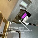
Choose Switch Location and Install: A discreet location like the storage cubby to the left of the steering wheel is ideal for hiding the switch. Remove the cubby. Use a drill to create a hole for mounting the SPDT switch. Optionally, use a Dremel to create a hole in the back of the cubby to pass the OBD2 cable through, allowing for a cleaner install.
-
Mount Switch and Route Cables: Mount the SPDT switch in the drilled hole in the cubby. Route the OBD2 splitter cables through the hole you created in the back of the cubby. Consider using an OBD2 extension cable with a 90-degree turn at the OBD2 port for added slack and easier cable management behind the dash.
-
Reinstall Cubby and Test: Reinstall the storage cubby. Connect your OBD2 devices to the splitter’s female ends. Test the switch to ensure it effectively powers each device independently.
Enjoy Seamless OBD2 Device Management
With your DIY OBD2 splitter and selector switch, you can now effortlessly manage multiple OBD2 devices. Tired of your radar detector for daily driving and want to use your OBD2 WiFi adapter for performance monitoring? Simply reach into your concealed cubby, flip the switch, and you’re ready to go. This modification provides a clean, efficient, and conflict-free way to maximize the utility of your car’s OBD2 port, enhancing both your driving experience and your vehicle’s diagnostic capabilities.