As a content creator for obd-de.com and an automotive repair expert, I’m here to provide you with an in-depth guide to Obd2 Terminal Identification. Understanding the OBD2 connector and its terminals is crucial for anyone involved in vehicle diagnostics, repair, or data analysis. This article expands upon the basics of OBD2, focusing specifically on how to identify each terminal and its function, empowering you to effectively utilize OBD2 for various automotive applications.
I. Understanding OBD2 and its Importance
On-Board Diagnostics II (OBD2) is a standardized system implemented in modern vehicles to monitor and report on their health. It acts as your car’s self-diagnostic system, providing access to a wealth of information about engine performance, emissions, and various other parameters. The OBD2 system communicates through a standardized 16-pin connector, typically located within easy reach of the driver’s seat.
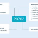
When that check engine light illuminates on your dashboard, it’s the OBD2 system signaling a potential issue. Mechanics use OBD2 scanners to interface with this system, retrieving diagnostic trouble codes (DTCs) and real-time data to pinpoint problems efficiently. This communication happens through the OBD2 connector, sending requests to the vehicle and receiving responses containing valuable data like speed, engine temperature, and fault codes.
Understanding OBD2: The malfunction indicator light signals potential vehicle issues diagnosable via an OBD2 scanner.
II. OBD2 Compatibility and History
Chances are, if you own a relatively new car, it’s OBD2 compliant. OBD2 became a standard requirement due to emissions regulations, originating in California with the California Air Resources Board (CARB) mandating OBD in new cars from 1991 onwards for emission control. The Society of Automotive Engineers (SAE) further standardized the protocol, including DTCs and the connector itself (SAE J1962).
The rollout of OBD2 was gradual but comprehensive:
- 1996: OBD2 mandated in the USA for cars and light trucks.
- 2001: Required in the EU for gasoline cars.
- 2003: Required in the EU for diesel cars (EOBD).
- 2005: OBD2 required in the US for medium-duty vehicles.
- 2008: US cars mandated to use ISO 15765-4 (CAN) as the OBD2 communication basis.
- 2010: OBD2 required in US heavy-duty vehicles.
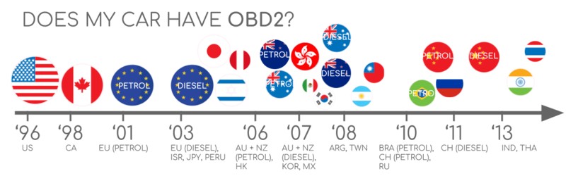
To quickly check if your car is OBD2 compliant, consider its origin and year of purchase:
OBD2 Compliance Guide: Check your vehicle’s origin and year of purchase to determine OBD2 compatibility.
III. The Future of OBD2: OBD3 and Beyond
While OBD2 remains relevant, the automotive landscape is evolving. Electric vehicles (EVs), for example, are not mandated to support OBD2 in the same way as combustion engine vehicles, and often utilize OEM-specific protocols like UDS. This makes accessing data from EVs more challenging, requiring reverse engineering efforts as seen in cases with Tesla, Hyundai/Kia, Nissan, and VW/Skoda.
Emerging standards like WWH-OBD (World Wide Harmonized OBD) and OBDonUDS (OBD on UDS) aim to modernize OBD communication by leveraging the UDS protocol, offering enhanced data richness and streamlined communication.
The concept of OBD3 envisions integrating telematics into vehicles for remote diagnostics and emission monitoring. This would involve vehicles automatically transmitting VIN and DTCs wirelessly to central servers, potentially streamlining emission checks and diagnostics. While offering convenience, OBD3 raises concerns about data privacy and surveillance.
Furthermore, the automotive industry is debating the future accessibility of OBD2 data for third-party services. Concerns about security and data ownership are leading to discussions about potentially restricting OBD2 access while driving, centralizing data collection with manufacturers. This could significantly impact the aftermarket OBD2 service industry.
OBD2 Future Challenges: Electric vehicles and industry discussions may lead to changes in OBD2 accessibility.
IV. OBD2 Standards and the OSI Model
OBD2 operates as a higher-layer protocol, similar to J1939, CANopen, and NMEA 2000, built upon lower-layer communication methods like CAN bus. The OBD2 standards encompass various aspects, including the connector specification, lower-layer protocols, and OBD2 parameter IDs (PIDs).
These standards can be visualized using the 7-layer OSI model, illustrating how OBD2 communication is structured. Both SAE and ISO standards contribute to different layers, reflecting US and EU standardization efforts. Notably, SAE J1979 and ISO 15031-5 are functionally equivalent, as are SAE J1962 and ISO 15031-3.
OBD2 in the OSI Model: Illustrating the layered structure of OBD2 communication standards in relation to CAN bus.
V. Deep Dive into the OBD2 Connector: SAE J1962 and Terminal Identification
The OBD2 connector, specified by SAE J1962 and ISO 15031-3, is your physical interface to your vehicle’s diagnostic system. It’s a 16-pin connector designed for easy access to vehicle data.
Understanding OBD2 Terminal Identification is Key: Effectively using an OBD2 scanner or any OBD2-based tool hinges on understanding the function of each pin within the connector. This knowledge enables you to:
- Verify power and ground: Ensure your diagnostic tool is properly powered.
- Identify communication lines: Locate the correct pins for CAN bus, K-line, or other communication protocols.
- Troubleshoot connection issues: Diagnose problems if your scanner is not communicating with the vehicle.
- Customize OBD2 applications: Develop custom solutions for data logging or vehicle monitoring.
Let’s examine the OBD2 connector pinout (Type A), which is commonly found in cars:
OBD2 Connector Pinout – Type A (SAE J1962):
| Pin | Wire Color (Typical) | Function | Protocol/Usage (Typical) |
|---|---|---|---|
| 1 | Optional | Manufacturer Discretion | OEM Specific |
| 2 | J1850 Bus+ | SAE J1850 VPW Bus (+) | SAE J1850 VPW |
| 3 | Optional | Manufacturer Discretion | OEM Specific |
| 4 | Chassis Ground | Chassis Ground | Ground |
| 5 | Signal Ground | Signal Ground | Ground |
| 6 | CAN High (J-2284) | CAN High | ISO 15765-4 (CAN) |
| 7 | K-Line (ISO 9141-2 & ISO 14230-4) | K-Line of ISO 9141-2 & ISO 14230-4 | ISO 9141-2, ISO 14230-4 (KWP2000) |
| 8 | Optional | Manufacturer Discretion | OEM Specific |
| 9 | Optional | Manufacturer Discretion | OEM Specific |
| 10 | J1850 Bus- | SAE J1850 PWM Bus (-) | SAE J1850 PWM |
| 11 | Optional | Manufacturer Discretion | OEM Specific |
| 12 | Optional | Manufacturer Discretion | OEM Specific |
| 13 | Optional | Manufacturer Discretion | OEM Specific |
| 14 | CAN Low (J-2284) | CAN Low | ISO 15765-4 (CAN) |
| 15 | L-Line (ISO 9141-2 & ISO 14230-4) | L-Line of ISO 9141-2 & ISO 14230-4 | ISO 9141-2, ISO 14230-4 (KWP2000) |
| 16 | Battery Power | Battery Voltage (Typically 12V or 24V) | Power Supply for Diagnostic Tools |

Key points about the OBD2 connector and terminal identification:
- Location: Typically found near the steering wheel, but its exact location can vary and may be hidden behind a panel.
- Pin 16 – Power: Provides battery voltage (usually 12V for cars, 24V for trucks), even when the ignition is off, to power diagnostic tools. Identifying this pin is crucial for verifying power supply to your scanner.
- Pin 4 & 5 – Ground: Provide ground connections (Chassis Ground and Signal Ground). Ensuring proper ground is essential for reliable communication.
- Pin 6 & 14 – CAN Bus: These are the CAN High and CAN Low pins, used for CAN bus communication as per ISO 15765-4. For modern vehicles using CAN, these pins are central to OBD2 communication. Identifying pins 6 and 14 is critical for CAN-based OBD2 tools and data loggers.
- Pin 7 & 15 – K-Line/L-Line: Used for older protocols like ISO 9141-2 and ISO 14230-4 (KWP2000). While less common in newer vehicles, these pins might still be present and relevant for diagnosing older cars. Identifying pins 7 and 15 is important when working with vehicles using these protocols.
- Pins 2 & 10 – J1850: Used for SAE J1850 VPW and PWM protocols, primarily in older GM and Ford vehicles respectively.
- Manufacturer Discretion (Optional Pins): Pins 1, 3, 8, 9, 11, 12, and 13 are reserved for manufacturer-specific uses. Their function can vary significantly between car brands and models, and information on these pins is typically OEM-proprietary.
VI. OBD2 Connector Types: Type A vs. Type B and Terminal Variations
While Type A is common in cars, you may encounter Type B OBD2 connectors, especially in medium and heavy-duty vehicles.
OBD2 Connector Types: Type A (cars) and Type B (trucks) with different power supply and physical characteristics.
Key differences between Type A and Type B OBD2 connectors and terminal usage:
- Power Supply: Type A typically provides 12V power, while Type B provides 24V, catering to the different electrical systems in cars versus heavy vehicles. Pin 16 terminal identification is therefore crucial to understand the voltage supplied.
- Physical Keying: Type B connectors have an interrupted groove, making them incompatible with Type A adapters. However, Type B adapters are generally backward compatible with Type A sockets.
- Communication Protocols and Pinout Similarities: Both types share similar pinouts for communication protocols (CAN, J1850, ISO 9141/14230). The core terminal identification for communication (pins 6, 14, 7, 15, 2, 10) remains largely consistent between Type A and Type B.
- Baud Rates: Cars (Type A) often use 500K baud rate for CAN, while heavy-duty vehicles (Type B) may use 250K or 500K. This is related to the communication protocol implemented on pins 6 and 14, but not directly to terminal identification itself.
Understanding these differences is important when selecting the correct OBD2 adapter and diagnosing vehicles of different types. However, the fundamental principles of OBD2 terminal identification remain the same for both connector types.
VII. OBD2 and CAN Bus: ISO 15765-4 and Terminal Usage for CAN Communication
Since 2008, CAN bus (ISO 15765-4) has been the mandatory lower-layer protocol for OBD2 in US vehicles. ISO 15765-4, also known as Diagnostics over CAN (DoCAN), standardizes the CAN interface for diagnostic equipment, focusing on the physical, data link, and network layers.
OBD2 and CAN Bus: Illustrating the relationship between OBD2 as a protocol and CAN bus as the communication medium.
Key aspects of OBD2 and CAN bus relevant to terminal identification:
- CAN High and CAN Low Terminals (Pins 6 & 14): ISO 15765-4 communication relies on correctly identifying pins 6 (CAN High) and 14 (CAN Low) on the OBD2 connector. Connecting your CAN-based OBD2 tool to these terminals is essential for establishing communication.
- Bit Rate and CAN ID Considerations: While terminal identification focuses on the physical pins, understanding that ISO 15765-4 specifies bit rates (250K or 500K) and CAN ID types (11-bit or 29-bit) is important for configuring your diagnostic tools correctly after physically connecting to the right terminals.
- OBD2 CAN Identifiers: OBD2 communication uses specific CAN IDs for requests and responses. Functional addressing (ID 0x7DF for 11-bit, 0x18DB33F1 for 29-bit) and physical addressing (0x7E0-0x7E7 for 11-bit) are used. While terminal identification is about the physical layer, knowing these IDs is crucial for interpreting the data transmitted over pins 6 and 14.
Example: Identifying CAN Bus Terminals for OBD2 Data Logging:
If you want to log OBD2 data using a CAN bus data logger, you need to:
- Locate the OBD2 connector in your vehicle.
- Identify pins 6 (CAN High) and 14 (CAN Low) using the OBD2 terminal pinout diagram.
- Connect your CAN logger to these pins (and power and ground pins as needed for the logger).
- Configure your CAN logger to listen for CAN traffic on the appropriate bit rate (typically 500K for cars).
- Start logging data and analyze the CAN messages, filtering for OBD2 specific IDs if needed.
Verifying Bit-rate and Terminal Connection:
Before extensive data logging, it’s good practice to verify your connection and bit-rate. You can use a CAN tool to send a CAN frame (e.g., an OBD2 request) at a specific bit rate (e.g., 500K) and check if it’s successfully transmitted and if you receive a response. This ensures you have correctly identified and connected to the CAN High and CAN Low terminals (pins 6 and 14) and are using the correct bit rate.
OBD2 Bit-rate and CAN ID Validation: Flowchart for systematically verifying communication parameters.
VIII. OBD2 Protocols Beyond CAN and Terminal Pin Relevance
While CAN bus is dominant, older vehicles may use other OBD2 protocols:
Five OBD2 Protocols: CAN (ISO 15765), KWP2000 (ISO 14230-4), ISO 9141-2, SAE J1850 VPW, and SAE J1850 PWM.
- ISO 14230-4 (KWP2000): Uses pin 7 (K-line) for communication.
- ISO 9141-2: Uses pin 7 (K-line) and optionally pin 15 (L-line) for communication.
- SAE J1850 VPW: Uses pin 2 (J1850 Bus+).
- SAE J1850 PWM: Uses pins 2 (J1850 Bus+) and 10 (J1850 Bus-).
Terminal Identification for Multi-Protocol Support:
If you’re working with a variety of vehicles, including older models, accurate OBD2 terminal identification becomes even more critical. You need to identify not only the CAN bus terminals (pins 6 & 14) but also the terminals for other protocols (pins 7, 15, 2, 10) to ensure your diagnostic tool can communicate with different vehicle types. Some diagnostic tools are designed to automatically detect the protocol in use, but understanding the pin assignments is crucial for troubleshooting and manual configuration.
IX. Practical Applications of OBD2 Terminal Identification
Beyond basic diagnostics, understanding OBD2 terminal identification is essential for various applications:
- Custom OBD2 Adapters and Cables: For specialized projects, you might need to create custom OBD2 adapter cables. Knowing the pinout allows you to wire the connector correctly for your specific needs.
- OBD2 Breakout Boxes: These tools provide easy access to each OBD2 terminal, allowing for voltage measurements, signal monitoring, and connection of test equipment. Terminal identification is fundamental to using breakout boxes effectively.
- Advanced Diagnostics and ECU Reprogramming: Some advanced diagnostic and ECU reprogramming procedures require direct access to specific OBD2 terminals for bypassing modules or establishing specific communication channels. Precise terminal identification is crucial to avoid damaging vehicle electronics.
- Vehicle Telematics and Data Logging: Developing custom telematics solutions or advanced data loggers often involves directly interfacing with the OBD2 connector. Identifying the correct terminals for power, ground, and communication buses is a fundamental step.
X. Safety Precautions When Working with OBD2 Terminals
While working with OBD2 terminals is generally safe, it’s important to follow basic precautions:
- Avoid Short Circuits: Be careful not to short circuit any terminals, especially the power (pin 16) and ground (pins 4 & 5) terminals. This can damage your diagnostic tool or the vehicle’s electrical system.
- Use Proper Tools: Use appropriate OBD2 connectors, adapters, and breakout boxes designed for automotive use.
- Consult Vehicle Documentation: If you are unsure about the OBD2 pinout or protocol for a specific vehicle, consult the vehicle’s service manual or reliable online resources.
- Disconnect Battery (Sometimes Recommended): For certain advanced procedures, it may be recommended to disconnect the vehicle’s battery to minimize the risk of electrical damage.
Conclusion: Mastering OBD2 Terminal Identification
OBD2 terminal identification is a foundational skill for anyone working with modern vehicle diagnostics and data. By understanding the function of each pin in the OBD2 connector, you gain the ability to effectively use diagnostic tools, troubleshoot communication issues, develop custom applications, and work safely with vehicle electronics. Whether you are a professional mechanic, a car enthusiast, or an automotive engineer, mastering OBD2 terminal identification will significantly enhance your capabilities in the automotive field.
For further learning, explore our Ultimate CAN Guide to deepen your knowledge of CAN bus and related automotive communication technologies.
Ready to put your OBD2 knowledge into practice? Explore our range of OBD2 data loggers and tools to start collecting and analyzing vehicle data today!
Recommended for you
OBD2 DATA LOGGER: EASILY LOG & CONVERT OBD2 DATA
CANEDGE2 – PRO CAN IoT LOGGER
[