Are you looking to diagnose the engine of a vintage vehicle that doesn’t have a standard OBD2 port? Many older cars and some specific applications utilize a 4-pin diagnostic connector instead of the now ubiquitous 16-pin OBD2 port. This DIY guide will walk you through creating a simple and effective OBD2 to 4-pin adapter, allowing you to use modern OBD2 scanners on these systems.
Disclaimer: Before we begin, it’s crucial to understand this is a DIY project. While this guide is based on a successful build, proceed at your own risk. Incorrect wiring can potentially damage your vehicle’s ECU or your diagnostic tool. We are not responsible for any adverse outcomes resulting from this modification.
Tools and Parts You’ll Need
To build your OBD2 to 4-pin adapter, gather the following tools and parts:
Tools:
- Wire strippers/cutters
- Needle-nose pliers
- Soldering iron (recommended for a robust connection)
- Molex crimping tool (optional, soldering is suggested as an alternative)
Parts:
- 4-Pin Connector (housing and pins suitable for 22-16AWG wire, insulation size 1.3-1.7mm)
- OBD-II Cable (with female OBD2 connector)
You can source these parts from electronic component suppliers online. Using a pre-made OBD-II cable simplifies the process, but you can also purchase a female OBD-II connector separately if you have spare wire and want to customize the length.
Wiring and Pinout: Understanding the Connections
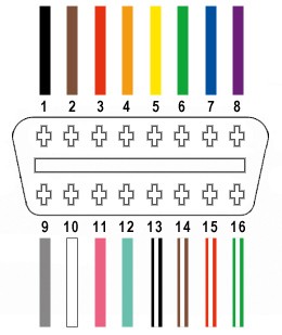
The OBD2 connector has 16 pins, but for this adapter, we only need to utilize four key connections:
- Pin 4 (Chassis Ground): This is the ground reference for the vehicle’s electrical system.
- Pin 6 (CAN High – J-2284): This is the CAN bus high signal wire for diagnostic communication.
- Pin 14 (CAN Low – J-2284): This is the CAN bus low signal wire for diagnostic communication.
- Pin 16 (Battery Power): This provides power to the OBD2 scanner.
These four pins are essential for basic OBD2 communication, particularly for reading diagnostic trouble codes and live data on vehicles that use a CAN bus protocol through a 4-pin connector.
Step-by-Step Guide to Building Your Adapter
Let’s get hands-on and build this adapter. Follow these steps carefully:
Step 1: Prepare the OBD-II Cable Wires
Begin by stripping back the outer sheath and shielding of the OBD-II cable to expose the individual wires inside. Identify the wires corresponding to OBD2 pins 4, 6, 14, and 16. These are often color-coded, but it’s always best to double-check your cable’s wiring diagram if available. Isolate and gently separate these four wires from the rest. Secure the unused wires with a zip tie to keep them out of the way during the adapter assembly.
Step 2: Prepare the Wire Ends for the 4-Pin Connector
The wires in many OBD-II cables are often a smaller gauge (e.g., 26AWG) than ideal for the pins in standard 4-pin connectors, which are typically designed for 22-16AWG. To ensure a secure connection, carefully strip approximately 3/8 inch of insulation from the end of each of the four selected OBD-II wires. To increase the wire thickness for a better fit in the 4-pin connector pins, fold the exposed wire strands over and twist them tightly. This effectively thickens the wire and improves contact within the pin. Slide a rubber seal (if provided with your 4-pin connector kit) onto each wire. These seals provide environmental protection to the finished connections.
Step 3: Attach Pins to the Wires
The pins for the 4-pin connector have two sets of prongs: one set to crimp onto the wire strands and another to crimp onto the wire insulation (rubber seal). Insert the prepared wire end into the pin, ensuring the wire strands align with the front set of prongs. Due to the smaller gauge wire, soldering is highly recommended at this stage to create a reliable electrical and mechanical connection. Use needle-nose pliers to hold the wire in place within the pin during soldering or crimping.
Step 4: Soldering the Wire to the Pin (Recommended)
Soldering provides a superior and more reliable connection, especially when dealing with smaller gauge wires. If you choose to solder, carefully apply solder to the area where the wire strands meet the pin’s prongs. Ensure the solder flows smoothly and creates a solid bond. If you’re new to soldering, numerous online resources and videos can provide helpful tips and techniques for successful soldering.
Step 5: Crimping the Pin (Alternative Method)
If you prefer crimping, or don’t have soldering equipment, use a Molex crimping tool for the best results. If a crimping tool is unavailable, you can carefully use needle-nose pliers. Fold one prong at a time over the wire, ensuring a tight crimp. For added security, you can use pliers to further flatten the crimped prongs, although this step should be approached with caution to avoid damaging the pin.
Step 6: Crimp the Seal Prongs
Slide the rubber seal up the wire until it sits between the second set of prongs on the pin. Use the same crimping technique (either with a crimping tool or needle-nose pliers) to fold these prongs over the rubber seal. This secures the seal in place, providing strain relief and environmental protection.
Step 7: Wire Pairing (Recommended for Signal Integrity)
While not strictly essential, it’s often recommended to twist pairs of wires, particularly for signal wires, to minimize electromagnetic interference and improve signal integrity. Pair and twist the wires as follows:
- Pin 4 (Orange – Ground) & Pin 16 (Green w/ White Stripe – Power)
- Pin 6 (Green – CAN High) & Pin 14 (Brown w/ White Stripe – CAN Low)
Twist each pair of wires together along their length. This step is beneficial for CAN bus communication.
Step 8: Insert Pins into the 4-Pin Connector Housing
Refer to the following pinout diagram and insert the completed pins into the corresponding slots of the 4-pin connector housing. Insert the pins from the rear of the connector until they lock into place with an audible “click”. Use needle-nose pliers to gently pull on each wire to ensure the pins are securely locked in their slots.
- Pin 14 (Brown w/ White Stripe – CAN Low) > Connector Slot A
- Pin 6 (Green – CAN High) > Connector Slot B
- Pin 16 (Green w/ White Stripe – Power) > Connector Slot C
- Pin 4 (Orange – Ground) > Connector Slot D
Adapter Complete!
Congratulations! You have successfully built your OBD2 to 4-pin adapter.
Testing Your Adapter
Before using your adapter regularly, test it to ensure it functions correctly. Connect the OBD2 end of your adapter to a compatible OBD2 scanner and the 4-pin end to your vehicle’s 4-pin diagnostic port. Turn on your vehicle’s ignition and attempt to communicate with the ECU using your scanner. Successful communication, error code reading, and data streaming confirm the adapter is working as intended.
This DIY OBD2 to 4-pin adapter can be a valuable tool for diagnosing older vehicles and systems. Remember to always double-check your connections and proceed with caution when working with automotive electrical systems. If you encounter any issues or have questions, consult online forums or seek advice from experienced automotive technicians.