Connecting your car’s OBD2 port to a DB9 connector might seem straightforward, but many DIY enthusiasts, especially those venturing into car diagnostics with tools like Arduino and CAN bus shields, often encounter frustrating roadblocks. This guide dives into common issues and solutions when linking Obd2 To Db9, drawing insights from real-world experiences to help you get your project running smoothly.
Understanding the Basics: OBD2 and DB9
Before diving into troubleshooting, let’s clarify what we’re working with. OBD2 (On-Board Diagnostics II) is a standardized system used in most modern cars to monitor and report vehicle health. It’s accessed through a trapezoidal 16-pin connector, commonly found under the dashboard. This port provides access to a wealth of data, from engine RPM and speed to diagnostic trouble codes.
DB9, on the other hand, is a 9-pin D-subminiature connector, frequently used for serial communication. In the context of OBD2, a DB9 connector is typically used as an intermediary interface to bridge the OBD2 port to devices that utilize serial or CAN bus communication, such as microcontrollers, CAN bus shields, or older diagnostic tools.
The OBD2 to DB9 cable acts as a physical adapter, re-routing specific pins from the OBD2 connector to the DB9 connector. This is crucial because not all OBD2 pins are relevant for every application. For example, when working with CAN bus data, you’re primarily interested in the CAN High and CAN Low pins of the OBD2 port.
Common Challenges with OBD2 to DB9 DIY Setups
Many DIY projects involve reading real-time data from a car’s OBD2 port for custom dashboards, data logging, or performance monitoring. Users often try to interface with the OBD2 port using microcontrollers like Arduino and CAN bus shields. However, this is where issues frequently arise. Let’s explore some common pitfalls:
1. Incorrect Wiring and Pinouts
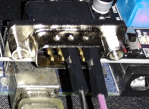
The most frequent culprit is incorrect wiring between the OBD2 and DB9 connectors. Creating your own OBD2 to DB9 cable requires precise knowledge of pin assignments. While there are standard pinouts, variations and errors can easily occur.
Problem: Incorrectly wired pins can lead to no communication, erratic data, or even potential damage to your car’s electronics or your interface device.
Solution:
- Double-check your sources: If you’re following a wiring diagram, ensure it’s from a reputable source and specifically for your intended application (e.g., CAN bus interface).
- Multimeter testing is essential: After wiring your cable, meticulously test the continuity between corresponding OBD2 and DB9 pins using a multimeter. This verifies that each pin is correctly connected to its intended counterpart.
2. CAN Bus Communication Issues
OBD2 often utilizes the CAN (Controller Area Network) bus protocol for communication, especially for accessing powertrain-related data. If you’re aiming to read engine RPM, speed, or other sensor data, you’ll likely be working with CAN bus.
Problem: Setting up CAN communication correctly involves more than just physical wiring. Issues can stem from:
- Incorrect CAN bus speed (baud rate): OBD2 CAN bus typically operates at 500 kbps. Your CAN shield and code must be configured to match this speed.
- CAN shield initialization errors: Problems with the CAN shield itself, its initialization in your code, or conflicts with other hardware can prevent communication.
- Filtering and masking: CAN bus communication involves message IDs. You might need to configure filters and masks in your CAN shield setup to receive the specific data you’re interested in.
Solution:
- Verify CAN shield initialization: Ensure your code correctly initializes the CAN shield library and sets the baud rate to 500 kbps. Refer to your CAN shield’s documentation for specific initialization procedures.
- Check for basic CAN communication: Use basic CAN bus example sketches to test if your CAN shield is transmitting and receiving data at all. This can help isolate if the problem is with the CAN shield itself or with the OBD2 interface.
- Implement proper CAN message requests: To get data like engine RPM or speed, you need to send specific CAN messages (requests) to the car’s ECU (Engine Control Unit). These requests follow OBD2 standards (like Service 01 PIDs – Parameter IDs).
3. Code and Library Compatibility
Working with OBD2 and CAN bus often requires specific libraries for your microcontroller platform (e.g., Arduino).
Problem:
- Library issues: Incorrect library installation, outdated libraries, or compatibility problems between libraries and your hardware can lead to code malfunctions.
- Code errors: Even with the correct libraries, errors in your code logic, message formatting, or data parsing can prevent successful communication and data retrieval.
- Lack of response handling: Your code needs to handle responses from the car’s ECU after sending requests. This involves checking for valid responses and extracting the data correctly.
Solution:
- Use reliable libraries: Stick to well-documented and community-supported CAN bus libraries for your chosen platform. For Arduino with Seeed CAN shield, the “mcp_can.h” library (as used in the original post’s code) is a common starting point.
- Start with example code: Begin with basic example sketches provided with your CAN shield library or from reputable online resources. Test these examples first to ensure your basic setup is working before attempting more complex code. The Seeed Studio example mentioned in the original post (Seeed-Studio/CAN_BUS_Shield/tree/master/examples/OBDII_PIDs) is a good starting point, but needs careful review.
- Implement response handling: Your code should include logic to:
- Send OBD2 request messages (e.g., for RPM – PID 0x0C, for speed – PID 0x0D).
- Check for incoming CAN messages.
- Filter for response messages (typically from IDs in the 0x7E8 range, as mentioned in the code).
- Parse the response data to extract the desired values (RPM, speed, etc.).
4. “Spamming” Issue and CAN Shield Behavior
The original poster observed the CAN shield “spamming” messages even after sending a single request.
Problem: This behavior, while seemingly unusual, can be related to:
- CAN shield configuration: Some CAN shields might have default settings that cause them to continuously transmit or monitor the CAN bus even without explicit instructions.
- Code loop behavior: If your code is not structured correctly, it might be repeatedly sending the same request message in a tight loop, leading to continuous transmission.
- Lack of proper delay: Insufficient delays between CAN message transmissions can also contribute to bus overload and the appearance of “spamming.”
Solution:
- Review CAN shield examples and documentation: Understand the expected behavior of your CAN shield based on its documentation and example code.
- Examine code loop logic: Carefully review your code’s
loop()function to ensure you’re not unintentionally sending requests repeatedly without waiting for responses or implementing proper delays. - Implement delays: Add appropriate
delay()functions after sending CAN messages to prevent overwhelming the CAN bus and allow time for responses. However, excessively long delays can also hinder real-time data acquisition. Experiment to find a balance.
Moving Forward with Your OBD2 to DB9 Project
Troubleshooting OBD2 to DB9 connections requires a systematic approach. Start with the basics:
- Verify your OBD2 to DB9 wiring meticulously. Use a multimeter to confirm pin continuity.
- Focus on CAN bus setup. Ensure correct baud rate, CAN shield initialization, and message formatting in your code.
- Begin with simple example code to test basic CAN communication before tackling complex OBD2 requests.
- Implement proper request/response handling in your code to retrieve and process data effectively.
- Consult your CAN shield’s documentation and community forums for specific troubleshooting tips and code examples.
By addressing these potential issues step-by-step, you can overcome common challenges and successfully establish a reliable OBD2 to DB9 connection for your DIY car diagnostics and data acquisition projects. Remember to always prioritize safety and double-check your connections before interfacing with your vehicle’s electronic systems.