Have you ever been puzzled by the sudden appearance of a ‘check engine light’ in your car? The frustration of not knowing the issue and the anticipation of a mechanic visit can be unsettling. Fortunately, with the power of Obd2 To Serial technology, you can take control of your car’s diagnostics right from your computer. The OBD-II UART, a clever piece of hardware, bridges the gap between your vehicle’s complex systems and your personal devices like laptops, embedded microcontrollers, or versatile single-board computers such as Raspberry Pi or Beaglebone Black. This guide will illuminate the path to understanding and utilizing OBD2 to Serial connections for effective car diagnostics.
What You Will Learn
This tutorial is designed to empower you with the knowledge to:
- Understand the components of the OBD-II UART interface.
- Grasp the fundamentals of OBD-II commands for vehicle communication.
- Establish a direct serial connection with your computer via FTDI for data access.
- Integrate the OBD-II UART with an Arduino microcontroller to display real-time vehicle data on an LCD screen.
Essential Tools and Materials
To embark on this diagnostic journey, ensure you have the following:
Materials:
- OBD-II UART Module
- FTDI Basic Breakout Board (for computer connection)
- Arduino Uno or compatible microcontroller (for LCD display setup)
- Serial LCD Screen (optional, for Arduino setup)
- Jumper Wires
- OBD-II to DB9 Cable
- Male Headers
Tools:
- Soldering Iron
- Solder
- Laptop
Recommended Background Knowledge
This guide assumes a basic understanding of electronics and serial communication. If you’re new to these areas, we recommend reviewing these helpful resources:
[
Through-Hole Soldering Guide
](https://learn.sparkfun.com/tutorials/how-to-solder-through-hole-soldering) Learn the essential techniques for through-hole soldering.
[
Serial Communication Explained
](https://learn.sparkfun.com/tutorials/serial-communication) Explore the concepts of asynchronous serial communication, UARTs, and baud rates.
[
Working with Wires: A Beginner’s Guide
](https://learn.sparkfun.com/tutorials/working-with-wire) Master the basics of stripping, crimping, and handling wires.
[
Introduction to Arduino
](https://learn.sparkfun.com/tutorials/what-is-an-arduino) Discover what Arduino is and its potential in various projects.
[
Understanding Hexadecimal Numbers
](https://learn.sparkfun.com/tutorials/hexadecimal) Learn to interpret and convert hexadecimal numbers.
[
Getting Started with OBD-II Systems
](https://learn.sparkfun.com/tutorials/getting-started-with-obd-ii) An overview of OBD-II protocols for automotive communication.
OBD-II UART Board: An Overview
On-Board Diagnostics, Second Generation (OBD-II) is a standardized system that revolutionized vehicle emission control and diagnostics. Originating in the US in 1994 and becoming mandatory for all US vehicles from 1996 onwards, OBD-II standards have been adopted globally. It mandates a standard Diagnostic Link Connector (DLC) in vehicles and a uniform communication protocol with the vehicle’s computer, known as the ECU (Electronic Control Unit).
Connecting to the OBD bus unlocks a wealth of vehicle data, including:
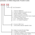
- Malfunction Indicator Light (MIL) status
- Diagnostic Trouble Codes (DTCs)
- Inspection and Maintenance (I/M) readiness
- Freeze frame data
- Vehicle Identification Number (VIN)
- Real-time parameters (speed, RPM, temperature, etc.)
For deeper insights into OBD-II protocols, refer to Wikipedia’s OBD-II article.
The STN1110 chip on the OBD-II UART board is a key component. It acts as an OBD to UART interpreter, translating OBD-II protocols into simple serial UART messages. Fully compatible with the popular ELM327 command set, the STN1110 offers enhanced features and performance. ScanTool provides extensive resources on the STN1110 on their website.
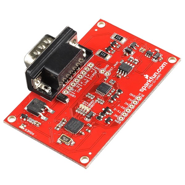
OBD-II UART Board Schematic
The OBD-II UART board is designed with both the STN1110 and MCP2551 chips, enabling access to both CAN and OBD-II protocols. The complete schematic is available for download.
The STN1110 microcontroller manages communication across CAN, ISO, and J1850 transceivers. The board incorporates voltage regulation to 5V and 3.3V to ensure proper operation of all components. Power is supplied through the DB9 connector.
Pin Configuration
The OBD-II UART board provides two connection interfaces:
-
6-Pin FTDI Compatible Header: Located on the board edge, this header is designed for FTDI Basic boards, providing TX, RX, and GND for UART communication.
-
8-Pin Header: Situated near the DB9 connector, this header allows access to VBAT, CAN bus, LINE bus, and J1858 bus, along with a ground pin.
Now that we’ve explored the board’s features, let’s proceed to setting up your first communication link.
Establishing Initial Communication
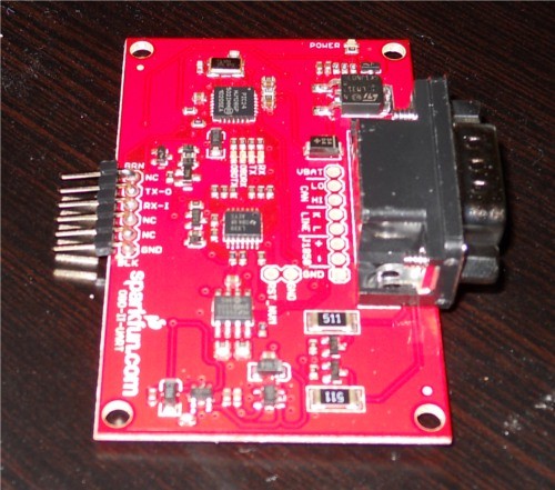
Soldering Header Pins
For reliable connections to external components like an FTDI Basic or Arduino, soldering headers to the OBD-II UART board is essential. For FTDI connections, solder male headers into the 6-pin header row. Once soldered, your board will resemble the image below.
OBD-II UART board after soldering right-angle male headers for easy connection.
Connecting to Your Vehicle’s OBD Port
Locate the OBD port in your vehicle. Its position can vary by car model, so consult your vehicle’s owner manual if needed.
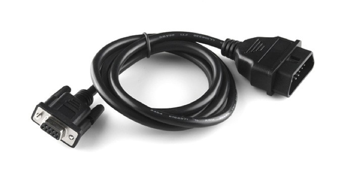
Once found, connect the OBD-to-DB9 cable to your vehicle’s OBD port.
A standard OBD-II to DB9 cable used for connecting to diagnostic tools.
The cable connector usually fits snugly into the OBD port. Connect the DB9 end of the cable to the OBD-II UART board after securely connecting to the vehicle.
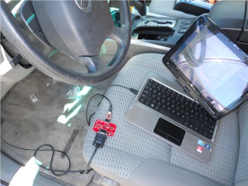
Serial Port Connection Setup
With headers soldered and the OBD-DB9 cable connected to your vehicle and OBD-II UART board, you can establish serial communication using an FTDI Basic breakout board. The FTDI pinout aligns with the 6-pin header on the OBD-II UART, utilizing TX, RX, and GND. Connect the FTDI board to your computer via a mini-USB cable.
Open a serial terminal application on your computer and configure it with the following settings:
- Baud Rate: 9600 bps
- Data bits: 8
- Stop bits: 1
- Parity: None
Once your serial terminal is ready, communication with the OBD-II UART board is achieved through AT commands. These commands are initiated with “AT” and are case-insensitive. A comprehensive list of AT commands is available in the ELM327 command set datasheet.
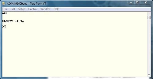
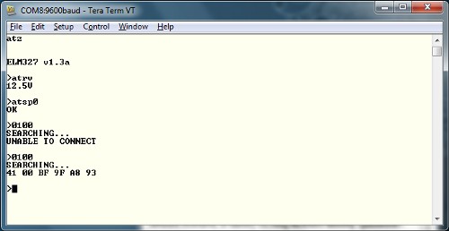
To begin, type “ATZ” in your terminal and press “Enter”. This command resets the OBD-II UART board. You should observe LEDs flashing on the board, followed by the startup prompt in your terminal.
Garbled characters indicate incorrect serial port settings. Verify your settings if this occurs.
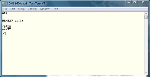
Upon successful communication, test reading the system voltage by sending “ATRV” and pressing “Enter”. The board should respond with the system voltage, which should match your vehicle’s battery voltage.
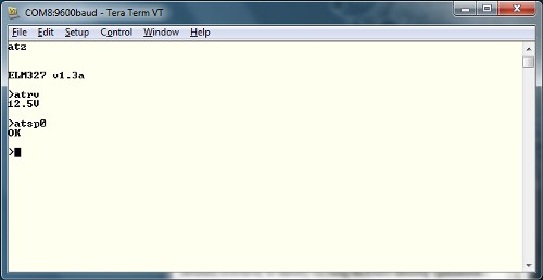
To access vehicle-specific OBD parameters, the correct OBD protocol must be set. The OBD-II UART board simplifies this by automatically detecting the protocol. Ensure your vehicle’s ignition is in the ‘On’ position (engine not necessarily running). Send the command “ATSP0” to initiate auto-protocol detection. The board will respond with “OK” upon successful detection.
With protocol detection complete, you can now send OBD commands to retrieve vehicle data.
Understanding OBD Commands
OBD Command Structure
OBD commands are composed of hexadecimal codes represented as ASCII characters. Most commands consist of two or more hexadecimal pairs, although some use only one.
The first hexadecimal pair indicates the OBD mode, and subsequent pairs specify the Parameter ID (PID) for the requested data within that mode. While OBD-II defines 10 modes, not all are supported by every vehicle. Consult your vehicle’s documentation to identify supported modes and PIDs.
| Mode Number | Mode Description |
|---|---|
| 01 | Show current data |
| 02 | Show freeze frame data |
| 03 | Show diagnostic trouble codes |
| 04 | Clear trouble codes & stored values |
| 05 | Oxygen sensor monitoring test results |
| 06 | On-board monitoring test results |
| 07 | Show pending trouble codes |
| 08 | Control operation of component |
| 09 | Request vehicle information |
| 0A | Show permanent trouble codes |
For detailed information on OBD PIDs, visit Wikipedia’s OBD-II PIDs page. Vehicle manufacturers may also implement proprietary parameters beyond the standard list. The ELM327 AT Commands datasheet is a valuable resource for further exploration.
PID 00 is universally supported in OBD-compliant vehicles. It returns a list of PIDs supported by the vehicle. In your serial terminal, send “0100” to query supported PIDs in mode 01.
OBD responses follow a consistent structure. The first byte (e.g., 0x41) indicates the requested mode (0x40 + 0x01). The second byte (e.g., 0x00) is the requested parameter. Subsequent bytes contain the response data. In this example, 0xBF, 0x9F, 0xA8, and 0x93 represent the supported PIDs.
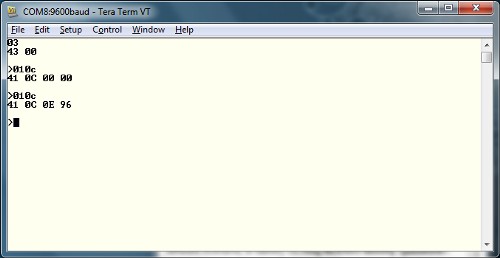
Another common parameter is Engine RPM. Send the command “010C”. The response will be in hexadecimal.
The response structure remains the same: 0x41 (mode 01), 0x0C (RPM parameter). The data 0x0E 0x96 converts to a decimal value of 3734. Since RPM is in quarter units, divide by 4 for an idling RPM of 933.
Explore the ELM327 datasheet for more PIDs to test. Next, we’ll integrate the OBD-II UART with an Arduino.
Integrating with Arduino
Arduino Connection Guide
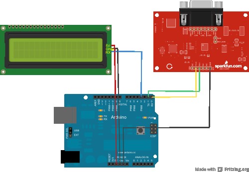
Beyond direct computer connection, you can interface the OBD-II UART with an Arduino and display data on an LCD for embedded applications. For this setup, you’ll need an Arduino Uno (or 5V compatible board), jumper wires, and a serial LCD.
Only 6 connections are required between the devices. Follow the diagram and table below for wiring.
| Arduino Pin | Serial LCD Pin | OBD-II-UART Pin |
|---|---|---|
| GND | GND | GND |
| 5V | 5V | None |
| D3 | Rx | None |
| D0(Rx) | None | Tx-O |
| D1(Tx) | None | Rx-I |
Download the Arduino sketch here or find the latest version on GitHub. Disconnect the OBD-II UART RX line from Arduino TX-0 during code upload to prevent potential issues.
Note that the Arduino is not powered by the OBD-II board. Power the Arduino separately via USB or a battery supply.
Arduino Sketch Explanation
The example sketch facilitates communication between the Arduino, OBD-II UART, and LCD. It utilizes the SoftwareSerial library for LCD communication.
#include <softwareserial.h>

// SoftwareSerial instance for LCD control (Arduino D3 to LCD Rx)
SoftwareSerial lcd(2,3);

char rxData[20];
char rxIndex=0;

int vehicleSpeed=0;
int vehicleRPM=0;
In the setup() function, serial communication for both LCD and OBD-II UART is initialized at 9600 bps. The LCD is cleared, and “Speed” and “RPM” headers are printed. The OBD-II board is reset.
void setup(){
  lcd.begin(9600);
  Serial.begin(9600);

  lcd.write(254);
  lcd.write(1);

  lcd.print("Speed: ");
  lcd.write(254);
  lcd.write(128+64);
  lcd.print("RPM: ");

  delay(1500);
  Serial.println("ATZ");
  delay(2000);
  Serial.flush();
}
The loop() function sets cursor positions, clears old LCD data, queries the OBD-II UART for speed and RPM, converts the received data, and displays it on the LCD.
void loop(){
  Serial.flush();

  lcd.write(254);
  lcd.write(128+8);
  lcd.print("     ");
  lcd.write(254);
  lcd.write(128+8);

  Serial.println("010D");
  getResponse();
  getResponse();
  vehicleSpeed = strtol(&rxData[6],0,16);
  lcd.print(vehicleSpeed);
  lcd.print(" km/h");
  delay(100);

  Serial.flush();

  lcd.write(254);
  lcd.write(128 + 69);
  lcd.print("     ");
  lcd.write(254);
  lcd.write(128+69);

  Serial.println("010C");
  getResponse();
  getResponse();
  vehicleRPM = ((strtol(&rxData[6],0,16)*256)+strtol(&rxData[9],0,16))/4;
  lcd.print(vehicleRPM);
  delay(100);
}
The getResponse() function handles serial data reception, storing characters until a carriage return is received, and then null-terminates the buffer.
void getResponse(void){
  char inChar=0;
  while(inChar != 'r'){
    if(Serial.available() > 0){
      if(Serial.peek() == 'r'){
        inChar=Serial.read();
        rxData[rxIndex]='';
        rxIndex=0;
      }
      else{
        inChar = Serial.read();
        rxData[rxIndex++]=inChar;
      }
    }
  }
}
Further Exploration and Resources
With a solid foundation in OBD2 to Serial communication, you can now customize the example sketch to access parameters specific to your vehicle.
Software Resources
Explore free software for visualizing OBD data in graphs and meters without extensive programming.
GitHub Repository: OBDII_UART/Software
Now that you’ve successfully set up your OBD II UART, integrate it into your unique projects!
For deeper learning, explore these resources:
[
CAN-BUS Shield Hookup Guide
](https://learn.sparkfun.com/tutorials/can-bus-shield-hookup-guide) Introduction to CAN-Bus shield applications.
[
Getting Started with OBD-II
](https://learn.sparkfun.com/tutorials/getting-started-with-obd-ii) Comprehensive guide to OBD-II protocols.
[
AST-CAN485 Hookup Guide
](https://learn.sparkfun.com/tutorials/ast-can485-hookup-guide) Learn about the AST CAN485 for industrial device interfacing.
By leveraging OBD2 to Serial technology, you gain direct access to your vehicle’s diagnostic data, empowering you to understand and interact with your car on a deeper level. Whether for personal diagnostics, custom dashboards, or advanced automotive projects, the possibilities are vast.