Disclaimer: Please be aware that this guide is intended for informational purposes only. I am not a professional mechanic, and this is based on my personal experience. Attempting this DIY project is at your own risk. Improper wiring can potentially damage your vehicle’s ECU or other systems. I am not responsible for any adverse outcomes resulting from following these instructions. Proceed with caution and ensure you understand each step before proceeding.
This guide will walk you through creating a simple Obd2 To Usb Pinout cable. This cable can be used for basic car diagnostics using software that supports OBD2 communication via USB. It’s a project suitable for DIY enthusiasts who want to delve into basic automotive diagnostics.
Tools and Parts You’ll Need
Before you begin, gather these tools and parts:
- Wire strippers/cutters: Essential for preparing the wires.
- Needle-nose pliers: Helpful for handling small components and crimping.
- Molex crimping tool (Recommended but not required): A proper crimping tool ensures secure connections, but pliers can be used as a substitute with careful technique.
- Soldering iron (Recommended): Soldering provides a more reliable electrical connection, especially with thin wires.
- 4-pin connector: (link to part used; pin/wire size = 22-16AWG; insulation/seal size = 1.3-1.7mm) – This connector will interface with the OBD2 cable.
- OBD-II Cable: (link to part used) – Provides the OBD2 connector end.
If you have spare wires and only need a short cable, you can purchase just the female OBD-II connector and use your own wires to connect to the 4-pin connector, potentially saving some cost. Ensure your wire gauge is compatible with the 4-pin connector you choose.
Understanding the OBD2 Connector Pinout for USB Conversion
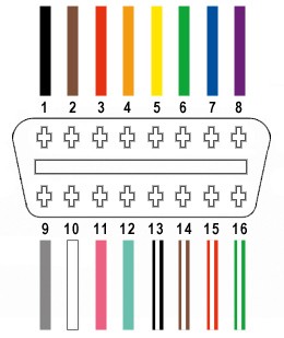
The OBD2 connector has 16 pins, but for this USB conversion, we only need to focus on four crucial pins for basic CAN bus communication:
- Pin 4 (Chassis Ground): Provides the ground reference (Orange wire in the specified OBD2 cable).
- Pin 6 (CAN [J-2234] High): Carries the CAN bus high signal (Green wire in the specified OBD2 cable).
- Pin 14 (CAN [J-2234] Low): Carries the CAN bus low signal (Brown w/white stripe wire in the specified OBD2 cable).
- Pin 16 (Battery Power): Provides power to the OBD2 device (Green w/white stripe wire in the specified OBD2 cable).
These four pins are essential for establishing a basic communication link to your vehicle’s CAN bus system, which is commonly used for diagnostic purposes.
Step-by-Step Guide to Building Your OBD2 to USB Cable
Follow these steps to assemble your OBD2 to USB pinout cable:
Step 1: Prepare the OBD2 Cable Wires
The initial step involves preparing the OBD2 cable for wiring. It’s often recommended to twist pairs of wires for signal integrity, although for this simple setup, it’s less critical but still good practice.
Begin by carefully removing the outer sheath and shielding from a section of the OBD2 cable to expose the internal wires. Identify and separate the four wires you’ll be using: Pin 4 (Orange – Ground), Pin 6 (Green – CAN High), Pin 14 (Brown w/white stripe – CAN Low), and Pin 16 (Green w/white stripe – Battery Power). Bundle the remaining 12 unused wires and secure them with a zip tie to keep them out of the way.
Step 2: Prepare the Wires for the 4-Pin Connector
A slight challenge with the specified parts is that the wires in the OBD2 cable (OBD2C) are 26AWG, while the pins for the 4-pin connector (4PC) are designed for 22AWG wires. This means the OBD2 cable wires are a bit thin for optimal crimping.
To compensate, carefully strip approximately 3/8″ of insulation from the end of each of the four selected wires. Fold the exposed wire strands back over themselves and twist them tightly to effectively thicken the wire gauge. This will help ensure a better fit and connection within the 4-pin connector pins.
The 4-pin connector kit should include rubber seals. Slide one rubber seal onto each of the four prepared wires. These seals provide environmental protection and strain relief at the connector.
Step 3: Attach Wires to 4-Pin Connector Pins
Now, take the pins for the 4-pin connector. Each pin has two sets of prongs. The front prongs are designed to crimp onto the exposed wire, while the rear prongs crimp onto the wire insulation/seal.
Insert the prepared and thickened wire into the front of a pin, ensuring the exposed wire aligns with the front prongs. You’ll notice that the 26AWG wire is indeed quite small compared to the pin. Using needle-nose pliers can be very helpful to hold the wire in position during the next step, especially if you choose to solder.
Step 4: Soldering (Recommended) or Crimping the Wires
At this stage, you have two options for securing the wire to the connector pin: soldering or crimping.
Soldering (Recommended): Soldering provides a robust and electrically sound connection, which is particularly beneficial given the thin wires. If you choose to solder, carefully apply solder to the area where the wire is inserted into the pin. Ensure the solder flows and creates a solid connection.
Crimping (Alternative): If you have a Molex crimping tool, use it to crimp the front prongs of the connector pin securely around the wire. If you don’t have a crimping tool, needle-nose pliers can be used as a substitute. Carefully and gradually fold one prong over the wire using the pliers, then repeat for the other prong. Take your time to ensure a tight crimp. For added security, you can gently squeeze the crimped prongs further with the pliers, but avoid excessive force.
Step 5: Crimp the Seal Prongs
Once the wire is secured to the pin, slide the rubber seal up the wire until it sits between the rear set of prongs on the connector pin. Use the same crimping technique as before (either with a crimping tool or needle-nose pliers) to fold the rear prongs over the rubber seal. This crimps the seal in place, providing strain relief and environmental protection.
Step 6: Wire Pairing (Optional but Recommended)
While not strictly necessary for basic functionality, it’s good practice to twist the wires in pairs to potentially reduce electromagnetic interference. Pair the wires as follows:
- Pin 4 (Orange – Ground) with Pin 16 (Green w/white stripe – Battery Power)
- Pin 6 (Green – CAN High) with Pin 14 (Brown w/white stripe – CAN Low)
Twist each pair together gently.
Step 7: Insert Pins into the 4-Pin Connector Housing
Refer to the following pinout diagram to insert the pins into the correct slots of the 4-pin connector housing. The connector slots are typically labeled A, B, C, and D.
- Pin 14 (Brown w/white stripe – CAN Low): Insert into connector slot A
- Pin 6 (Green – CAN High): Insert into connector slot B
- Pin 16 (Green w/white stripe – Battery Power): Insert into connector slot C
- Pin 4 (Orange – Ground): Insert into connector slot D
Push each pin into the rear of the connector housing until you hear a click. This click indicates that the pin is locked securely in place. You may need to use needle-nose pliers to gently pull the wire from the front to ensure the pin is fully seated and locked.
Completion and Testing
Congratulations! You have now completed your DIY OBD2 to USB pinout cable.
To test your cable, connect the OBD2 end to your vehicle’s OBD2 port and the 4-pin connector end to a suitable USB adapter or device that supports OBD2 communication. Use diagnostic software compatible with your chosen USB interface to check for vehicle error codes or monitor live data.
In my case, I successfully used this cable to check and clear a self-induced error code.
If any steps are unclear, please feel free to ask for clarification, and I’ll do my best to provide further explanation or photos. Remember to always double-check your wiring and connections before using the cable with your vehicle.