Creating your own OBD2 to 4-pin connector harness can be a useful skill for automotive diagnostics and customization. Whether you’re connecting to a specific system in your vehicle or building a custom diagnostic tool, understanding how to create this harness is valuable. This guide provides a step-by-step approach to building your own OBD2 to 4-pin connector, perfect for enthusiasts and those looking to delve deeper into their vehicle’s systems. Please note, this guide is for informational purposes and should be undertaken with caution and at your own risk. We are not responsible for any damage that may occur during this process.
Tools You’ll Need:
- Wire strippers/cutters
- Needle-nose pliers
- Molex crimping tool (optional, but recommended for a professional finish)
- Soldering iron and solder (recommended for a secure connection)
Parts Required:
- 4-pin connector (ensure it’s compatible with 22-16AWG wire and 1.3-1.7mm insulation/seal size) – Example Part
- OBD-II Cable (with a female OBD-II connector) – Example Part
Alternatively, to save on costs, you can source a female OBD-II connector separately and use spare wires you may have on hand, provided they are the correct gauge. Ensure your 4-pin connector is compatible with your wire size if you choose this route.
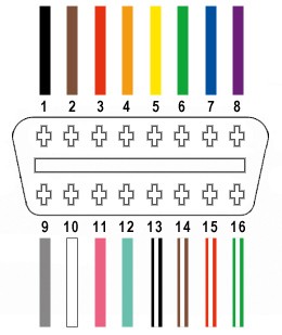
From the OBD-II connector’s 16 available pins, we will be utilizing only four essential wires for this harness:
- Pin 4: Chassis Ground (typically an orange wire in the example OBD2 cable – OBD2C)
- Pin 6: CAN (J-2234) High (typically a green wire in OBD2C)
- Pin 14: CAN (J-2234) Low (typically a brown wire with a white stripe in OBD2C)
- Pin 16: Battery Power (typically a green wire with a white stripe in OBD2C)
Step-by-Step Guide:
1) Preparing the OBD-II Cable Wires:
Many guides recommend twisting pairs of wires for signal integrity, especially for CAN bus communication. We’ll follow this best practice. Begin by carefully removing the outer sheath and shielding from your OBD-II cable to access the internal wires. Identify and separate the four wires you’ll be using (Pins 4, 6, 14, and 16 as listed above). Bundle the remaining 12 wires and secure them out of the way using a zip tie or electrical tape to keep your workspace tidy.
2) Preparing the Wire Ends for the 4-Pin Connector:
The wires in the example OBD-II cable (OBD2C) are 26AWG, which is slightly smaller than the 22AWG minimum recommended for the pins of the 4-pin connector (4PC). To ensure a secure and reliable connection, we need to slightly thicken the wire ends. Carefully strip approximately 3/8″ of insulation from the end of each of the four selected wires. Fold the exposed wire strands over onto themselves and twist them tightly. This effectively doubles the wire thickness at the point of connection. The 4-pin connector kit should include rubber seals. Slide one rubber seal onto each of the prepared wires.
3) Attaching Wires to 4-Pin Connector Pins:
The pins for the 4-pin connector have two sets of prongs. The front set is designed to crimp onto the exposed wire, and the rear set is for crimping onto the rubber seal, providing strain relief and environmental protection. Insert the prepared wire into a pin, ensuring the exposed wire aligns with the front set of prongs. The wire gauge might still appear small relative to the pin size. Using needle-nose pliers can help hold the wire in place for the next step, especially given the fine gauge of the wire.
4) Soldering the Wires (Recommended):
Soldering provides a robust and electrically sound connection, especially beneficial when working with finer gauge wires. If you are comfortable with soldering, this step is highly recommended. Solder the wire to the connector pin. Ensure the solder joint is clean and secure. For those new to soldering, numerous online resources, such as this helpful YouTube video, can provide valuable tips and techniques.
5) Crimping the Connector Pins (Alternative Method):
If you have a Molex crimping tool, use it to crimp the front prongs of the connector pin securely around the wire. For those without a dedicated crimping tool, needle-nose pliers can be used as an alternative. Carefully and at an angle, begin folding one prong over the wire, then repeat for the other prong. This YouTube video offers guidance on crimping techniques without a specialized tool. For added security, you can gently use pliers to further flatten the crimped prongs, although this might be considered overkill.
6) Securing the Rubber Seal:
Slide the rubber seal up the wire until it sits between the rear prongs of the connector pin. Using the same crimping technique as before (either with a crimping tool or needle-nose pliers), fold these rear prongs over the rubber seal. This secures the seal, providing strain relief and environmental protection to the connection.
7) Wire Pairing and Twisting:
It’s often recommended to twist certain wire pairs together, especially in CAN bus systems, to minimize electromagnetic interference and improve signal quality. Pair the wires as follows and twist each pair together:
- Pin 4 (orange – Chassis Ground) with Pin 16 (green w/white stripe – Battery Power)
- Pin 6 (green – CAN High) with Pin 14 (brown w/white stripe – CAN Low)
8) Inserting Pins into the 4-Pin Connector Housing:
Finally, insert the assembled pins into the 4-pin connector housing in the correct orientation as shown below:
- Pin 14 (brown w/white stripe – CAN Low) > Connector Slot A
- Pin 6 (green – CAN High) > Connector Slot B
- Pin 16 (green w/white stripe – Battery Power) > Connector Slot C
- Pin 4 (orange – Chassis Ground) > Connector Slot D
Push each pin firmly into the rear of the connector housing until you hear a distinct “click,” indicating that the pin is securely locked in place. Using needle-nose pliers can sometimes aid in gently pulling the wire from the front to ensure the pin is fully seated and locked.
Completion:
Congratulations! Your DIY OBD2 to 4-pin connector harness is now complete.
This harness can now be used for various applications, such as connecting OBD2 diagnostic tools to systems that utilize a 4-pin interface. Remember to always double-check your connections and consult your vehicle’s service manual for specific wiring diagrams and compatibility before use.
If any step in this guide is unclear, or if you require further clarification, please revisit the instructions and images carefully. Constructing this harness requires attention to detail and a basic understanding of automotive wiring. Always prioritize safety and accuracy when working with electrical systems in vehicles.