Want to dive deep into your car’s health? The On-Board Diagnostics II (OBD2) system is your gateway to real-time vehicle data. This comprehensive guide provides a practical introduction to the OBD2 protocol, focusing on understanding OBD2 live data and how you can access and interpret it. For deeper insights, you can also download our free PDF guide to understanding OBD2 live data and diagnostics.
What is OBD2 and Why is Live Data Important?
OBD2 is essentially your car’s internal health monitoring system. It’s a standardized protocol that allows you to retrieve diagnostic trouble codes (DTCs) and, crucially, OBD2 live data through a standard OBD2 connector.
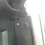
Ever seen that malfunction indicator light (often called the “check engine light”) illuminate on your dashboard? That’s OBD2 in action, signaling a potential issue within your vehicle. Mechanics use OBD2 scanners to diagnose these problems by connecting to the OBD2 16 pin connector, usually located near the steering wheel. These scanners send requests and receive responses containing valuable information like speed, engine temperature, fuel levels, and those all-important DTCs. This access to OBD2 live data parameters allows for faster and more accurate troubleshooting.
Is Your Car OBD2 Compliant?
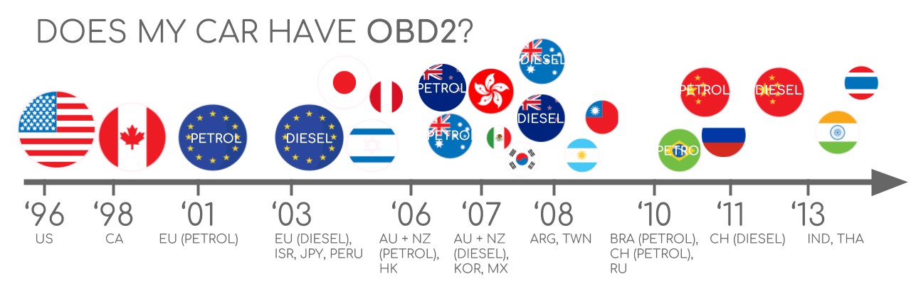
The good news is, if you own a relatively recent car, it’s probably OBD2 compliant! Most gasoline cars from 2001 onwards (in the EU) and 1996 onwards (in the USA), and diesel cars from 2004 onwards (in the EU) are mandated to support OBD2. While older cars might have a 16-pin connector resembling OBD2, it doesn’t guarantee OBD2 compliance.
To be sure, consider where and when your car was initially purchased. Regulations in the US and EU have driven OBD2 adoption. Check the vehicle’s manual or consult online resources to confirm your car’s compliance.
A Brief History of OBD2: From Emission Control to Modern Diagnostics
OBD2’s story begins in California, driven by the California Air Resources Board (CARB), who mandated on-board diagnostics in new cars from 1991 for emission control. The Society of Automotive Engineers (SAE) played a key role in standardizing the protocol, including DTCs and the OBD connector itself (standardized under SAE J1962).
The OBD2 standard rolled out progressively:
- 1996: OBD2 became mandatory in the USA for cars and light trucks.
- 2001: Required for gasoline cars in the EU.
- 2003: Extended to diesel cars in the EU (EOBD).
- 2005: OBD2 required for medium-duty vehicles in the US.
- 2008: US vehicles mandated to use ISO 15765-4 (CAN) as the foundation for OBD2 communication.
- 2010: OBD2 became mandatory for heavy-duty vehicles in the US.
Initially focused on emissions, OBD2 has become a powerful tool for broader vehicle diagnostics and accessing OBD2 live data streams.
The Future of OBD2: Trends and Challenges
OBD2 is evolving to meet the demands of modern vehicles and connected car technologies. Here are key trends shaping its future:
Electric vehicles (EVs) present a unique challenge. Legislated OBD2 was primarily for emission control. As EVs have no tailpipe emissions, they aren’t strictly required to support OBD2 in the traditional sense. In practice, many EVs don’t fully support standard OBD2 requests, often using OEM-specific protocols like UDS instead. However, reverse engineering efforts are making data access possible for some EV models like Tesla, Hyundai/Kia, Nissan, and VW/Skoda.
To address limitations in data richness and lower-layer protocols, alternatives like WWH-OBD (World Wide Harmonized OBD) and OBDonUDS (OBD on UDS) are emerging. These aim to enhance OBD communication using the UDS protocol as a base, offering more streamlined and advanced diagnostics.
The rise of OBD3 envisions adding telematics to vehicles. This could involve a radio transponder in cars, allowing for automatic transmission of Vehicle Identification Numbers (VIN) and DTCs via WiFi to central servers for remote emission checks and diagnostics. While convenient, this raises privacy and surveillance concerns. Devices like the CANedge2 WiFi CAN logger and CANedge3 3G/4G CAN logger already facilitate data transfer over WiFi/cellular networks.
However, the automotive industry is also discussing limiting third-party access to OBD2 data while driving, proposing to collect data centrally by manufacturers instead. This is argued to be for security reasons (reducing car hacking risks), but many view it as a move to control automotive big data and potentially disrupt the market for third-party OBD2 services.
OBD2 Standards: Connector, Protocols, and PIDs
OBD2 operates as a higher-layer protocol similar to J1939, CANopen, and NMEA 2000. It relies on a communication method, and in modern cars, that’s primarily CAN bus. OBD2 standards define the connector, lower-layer protocols, and OBD2 parameter IDs (PIDs), among other things.
These standards can be visualized within the 7-layer OSI model, with SAE and ISO standards covering various layers. SAE standards are generally associated with US OBD definitions, while ISO standards are prominent in the EU. Many standards are technically very similar, such as SAE J1979 and ISO 15031-5, or SAE J1962 and ISO 15031-3.
The OBD2 Connector (SAE J1962)
The 16-pin OBD2 connector, defined by SAE J1962 / ISO 15031-3, provides easy access to your car’s data. This connector, also known as the Data Link Connector (DLC), is typically located near the steering wheel, though sometimes it might be hidden.
Key features of the OBD2 connector:
- Pin 16 provides battery power, even when the ignition is off.
- The OBD2 pinout varies depending on the communication protocol used.
- CAN bus is the most common lower-layer protocol, utilizing pins 6 (CAN-H) and 14 (CAN-L).
OBD2 Connector – Type A vs. B
You might encounter both Type A and Type B OBD2 connectors. Type A is standard in cars, while Type B is more common in medium and heavy-duty vehicles.
While both types share similar pinouts, they differ in power supply output (12V for Type A, 24V for Type B) and often baud rates (500K for cars, 250K or 500K for heavy-duty vehicles).
Type B connectors have a distinguishing interrupted groove in the middle. Type B OBD2 adapter cables are compatible with both Type A and B sockets, but Type A adapters will not fit into Type B sockets.
OBD2 and CAN Bus (ISO 15765-4)
Since 2008, CAN bus (ISO 15765) has been the mandatory lower-layer protocol for OBD2 in US cars. ISO 15765-4, also known as Diagnostics over CAN (DoCAN), specifies how OBD2 operates over CAN (ISO 11898).
Key specifications of ISO 15765-4:
- CAN bus bit-rate: 250K or 500K.
- CAN IDs: 11-bit or 29-bit.
- Specific CAN IDs are designated for OBD requests and responses.
- Diagnostic CAN frame data length: 8 bytes.
- Max OBD2 adapter cable length: 5 meters.
OBD2 CAN Identifiers (11-bit, 29-bit)
OBD2 communication uses request and response messages. In most cars, 11-bit CAN IDs are used. The ‘Functional Addressing’ ID 0x7DF is used to query all OBD2-compatible ECUs for data on a requested parameter. ‘Physical Addressing’ requests to specific ECUs can be made using CAN IDs 0x7E0-0x7E7, though this is less common.
ECUs respond with 11-bit IDs in the range 0x7E8-0x7EF. The most common response ID is 0x7E8 (Engine Control Module – ECM), followed by 0x7E9 (Transmission Control Module – TCM).
Some vehicles, particularly vans and medium/heavy-duty vehicles, may use 29-bit CAN identifiers for OBD2. Here, the ‘Functional Addressing’ CAN ID is 0x18DB33F1. Responses use CAN IDs from 0x18DAF100 to 0x18DAF1FF, with typical examples being 0x18DAF110 and 0x18DAF11E. The response ID is sometimes represented in J1939 PGN format as PGN 0xDA00 (55808), which is reserved for ISO 15765-2 in the J1939-71 standard.
OBD2 vs. Proprietary CAN Protocols
It’s crucial to understand that your car’s ECUs primarily function using OEM-specific CAN protocols, not OBD2. Each manufacturer implements proprietary CAN protocols that are often unique to the vehicle brand, model, and year. Unless you are the OEM, interpreting this data is usually impossible without reverse engineering.
Connecting a CAN bus data logger to the OBD2 port might reveal OEM-specific CAN data, often broadcast at high rates (1000-2000 frames/second). However, many newer cars use a ‘gateway’ to block access to this data through the OBD2 port, allowing only OBD2 communication.
Think of OBD2 as an additional higher-layer protocol that operates alongside the OEM-specific protocols, rather than being fundamental to the vehicle’s core functions.
Bit-Rate and ID Validation
OBD2 can use two bit-rates (250K, 500K) and two CAN ID lengths (11-bit, 29-bit), creating four potential combinations. Modern cars commonly use 500K and 11-bit IDs, but tools should systematically verify this.
ISO 15765-4 provides a validation sequence to determine the correct combination. This process relies on the fact that OBD2-compliant vehicles must respond to a mandatory OBD2 request and that incorrect bit-rates will cause CAN error frames.
Newer versions of ISO 15765-4 also account for OBD communication via OBDonUDS in addition to OBDonEDS. This article mainly focuses on OBD2/OBDonEDS (OBD on emission diagnostic service as per ISO 15031-5/SAE J1979), which is prevalent in most non-EV cars. WWH-OBD/OBDonUDS is primarily used in EU trucks and buses.
To differentiate between OBDonEDS and OBDonUDS, advanced tools may send UDS requests (service 0x22, DID 0xF810) to check for OBDonUDS support.
Five Lower-Layer OBD2 Protocols
While CAN (ISO 15765) is dominant today, older cars (pre-2008) might use other lower-layer protocols for OBD2. Understanding these can be helpful when working with older vehicles. The connector pinout can sometimes indicate the protocol in use.
- ISO 15765 (CAN bus): Mandatory in US cars since 2008, now widely used.
- ISO14230-4 (KWP2000): Common in 2003+ Asian cars.
- ISO 9141-2: Used in EU, Chrysler & Asian cars (2000-2004).
- SAE J1850 (VPW): Primarily in older GM cars.
- SAE J1850 (PWM): Primarily in older Ford cars.
Understanding OBD2 Live Data Parameters (PIDs)
OBD2 data is transmitted over CAN bus using the ISO-TP transport protocol (ISO 15765-2). This protocol allows for messages larger than 8 bytes, which is necessary for transmitting things like VIN or DTCs. ISO-TP handles segmentation, flow control, and reassembly of these larger messages. However, much OBD2 live data fits within single CAN frames. In these cases, ISO 15765-2 uses ‘Single Frame’ (SF) format.
The OBD2 Diagnostic Message (SAE J1979, ISO 15031-5)
A simplified OBD2 CAN message includes an identifier, data length (PCI field), and data. The data section is further broken down into Mode, parameter ID (PID), and data bytes.
Example: OBD2 Request/Response for Live Data
Let’s look at an example of requesting and receiving OBD2 live data – specifically, vehicle speed.
To request vehicle speed, an external tool sends a message with CAN ID 0x7DF and two data bytes: Mode 0x01 and PID 0x0D. The car responds with CAN ID 0x7E8 and three data bytes, including the speed value in the 4th byte, 0x32 (decimal 50).
By consulting the OBD2 PID documentation for 0x0D, we can determine that 0x32 represents 50 km/h. This process is key to interpreting OBD2 live data.
The 10 OBD2 Services (Modes)
There are 10 standardized OBD2 diagnostic services, also known as modes. Mode 0x01 is crucial for accessing current, real-time or “live” data. Other modes are used for DTCs, freeze frame data, and more. Vehicles aren’t required to support all 10 modes, and OEMs may implement additional, non-standard modes.
In OBD2 messages, the mode is the second byte. In a request, the mode is directly included (e.g., 0x01). In the response, 0x40 is added to the requested mode value (e.g., 0x41 for a response to mode 0x01).
OBD2 Parameter IDs (PIDs) for Live Data
Within each OBD2 mode, parameter IDs (PIDs) identify specific data points. Mode 0x01, for instance, contains around 200 standardized PIDs for real-time data like speed, RPM, and fuel level. However, vehicles typically support only a subset of these PIDs.
One PID is particularly important: Mode 0x01 PID 0x00. If an emissions-related ECU supports OBD2 at all, it must support this PID. Responding to PID 0x00, the ECU indicates which PIDs from 0x01-0x20 it supports. This makes PID 0x00 a fundamental OBD2 compatibility test. Similarly, PIDs 0x20, 0x40, and so on, reveal support for subsequent PID ranges within mode 0x01.
Accessing and Interpreting OBD2 Live Data
To access and interpret OBD2 live data, you’ll typically use an OBD2 scanner or an OBD2 data logger. These tools send requests for specific PIDs and then decode the responses. Understanding the scaling and units for each PID is essential for converting the raw data bytes into meaningful physical values.
For quick reference, resources like our OBD2 PID overview tool are invaluable. These tools help you construct request frames and dynamically decode responses, making OBD2 live data analysis much easier.
How to Log and Analyze OBD2 Live Data – Practical Guide
Let’s walk through a practical example of logging OBD2 live data using a CANedge CAN bus data logger. The CANedge allows you to configure custom CAN frames for transmission, making it ideal for OBD2 applications.
Connect the CANedge to your vehicle using an OBD2-DB9 adapter cable.
#1: Test Bit-Rate, IDs & Supported PIDs
First, determine the correct bit-rate and CAN IDs for your vehicle. ISO 15765-4 outlines a process for this. You can use the CANedge to test:
- Send a CAN frame at 500K and check for successful transmission (if not, try 250K).
- Use the validated bit-rate for subsequent communication.
- Send ‘Supported PIDs’ requests (Mode 0x01, PID 0x00 and subsequent range queries) and review the responses.
- Response IDs will indicate 11-bit or 29-bit IDs.
- Response data will show supported PIDs.
Pre-configured settings are often available for these tests. Most post-2008 non-EV cars will support 40-80 PIDs using 500K bit-rate, 11-bit CAN IDs, and the OBD2/OBDonEDS protocol.
Tools like asammdf GUI can help review responses to ‘Supported PIDs’ requests. You might see multiple responses to a single request (ID 0x7DF) because it polls all ECUs. The ECM (0x7E8) often supports all PIDs supported by other ECUs. For efficiency, switch to ‘Physical Addressing’ (CAN ID 0x7E0) for subsequent requests to target specific ECUs.
#2: Configure OBD2 PID Requests for Data Logging
Once you know the supported PIDs and communication parameters, configure your CANedge to request the desired OBD2 live data parameters.
Consider these points:
- CAN IDs: Use ‘Physical Addressing’ request IDs (e.g., 0x7E0) to avoid multiple responses.
- Spacing: Add delays of 300-500 ms between requests to prevent ECU overload.
- Battery Drain: Use triggers to stop transmissions when the vehicle is inactive.
- Filters: Filter to record only OBD2 responses if OEM-specific CAN data is also present.
With configuration complete, the CANedge is ready to log raw OBD2 live data!
#3: DBC Decode Raw OBD2 Data for Analysis
To analyze and visualize the logged data, you need to decode the raw OBD2 live data into physical values. Decoding information is in ISO 15031-5/SAE J1979 and online resources. A free OBD2 DBC file simplifies this process in CAN bus software tools.
Decoding OBD2 data is more complex than standard CAN signals. Different PIDs use the same CAN ID (e.g., 0x7E8). Therefore, decoding requires considering the CAN ID, OBD2 mode, and PID – a form of multiplexing called ‘extended multiplexing’. DBC files can implement this extended multiplexing.
OBD2 Multi-Frame Communication Examples (ISO-TP)
While many examples use single-frame communication, OBD2 also uses multi-frame communication via ISO-TP for larger data payloads. Multi-frame communication involves flow control frames. Tools like CANedge MF4 decoders support ISO-TP for handling these responses.
Example 1: OBD2 Vehicle Identification Number (VIN) Retrieval
The Vehicle Identification Number (VIN) is often needed for telematics and diagnostics. To retrieve the VIN using OBD2, use mode 0x09 and PID 0x02.
The tool sends a Single Frame request (Mode 0x09, PID 0x02). The vehicle responds with a multi-frame response, starting with a First Frame indicating the total data length. The VIN itself is contained within subsequent Consecutive Frames, requiring ISO-TP capable software for proper reassembly.
Example 2: OBD2 Multi-PID Request (6x)
OBD2 allows requesting up to 6 mode 0x01 PIDs in a single request for increased efficiency. The ECU responds with data for supported PIDs, potentially using multi-frame responses. However, this method complicates decoding as the payload structure becomes request-specific, making generic DBC files less useful. It’s generally not recommended for practical data logging unless your tools have specific support for it.
Example 3: OBD2 Diagnostic Trouble Codes (DTCs)
OBD2 mode 0x03 (‘Show stored Diagnostic Trouble Codes’) retrieves emissions-related DTCs. No PID is needed in the request. The ECU responds with the number of stored DTCs and the DTC codes themselves (2 bytes per DTC). Multi-frame responses are used if more than two DTCs are stored.
DTCs are 2-byte values, categorized and coded according to ISO 15031-5/ISO 15031-6. Decoded DTC values can be looked up using online OBD2 DTC lookup tools.
Use Cases for OBD2 Live Data Logging
OBD2 live data logging has diverse applications across various industries:
Logging Data from Cars
OBD2 data is valuable for fuel efficiency analysis, driver behavior improvement, prototype testing, and insurance telematics.
Real-Time Car Diagnostics
OBD2 interfaces enable real-time streaming of OBD2 live data for vehicle diagnostics and troubleshooting.
Predictive Maintenance
IoT OBD2 loggers can monitor vehicles in the cloud for predictive maintenance, helping to prevent breakdowns.
Vehicle Black Box Logger
An OBD2 logger can serve as a ‘black box’ for vehicles, recording data for accident analysis, insurance claims, or general diagnostics.
Do you have a specific OBD2 live data logging use case? Contact us for expert advice!
For more introductory guides, explore our tutorials section or download our comprehensive ‘Ultimate Guide’ PDF to become an OBD2 and CAN bus expert.
Ready to start logging and understanding OBD2 live data?
Get your OBD2 data logger today!
Buy now Contact us
Recommended for you
OBD2 DATA LOGGER: EASILY LOG & CONVERT OBD2 DATA
CANEDGE2 – PRO CAN IoT LOGGER
CAN BUS INTERFACE: STREAMING OBD2 DATA WITH SAVVYCAN
(Note: While the “Ultimate CAN Guide PDF” is mentioned and linked, a separate “OBD2 Live Data PDF Free Download” was not explicitly created as it was not in the original article. The article itself serves as a comprehensive guide and implicitly encourages users to explore further resources, including the CAN guide, which is relevant to OBD2.)