For automotive enthusiasts and mechanics dealing with older vehicles, accessing the diagnostic data can be crucial. Before the standardized 16-pin OBD2 connector became the norm, vehicles utilized the 12-pin OBD1 system. Connecting your older car’s OBD1 system to modern PC-based diagnostic tools requires a special cable. While pre-made cables are available, building your own 12 Pin Obd1 To 16 Pin Obd2 cable can be a cost-effective and rewarding DIY project. This guide provides a step-by-step approach to creating your own OBD1 diagnostic cable for less than purchasing a commercial option.
Understanding OBD1 and the DIY Cable Solution
On-Board Diagnostics (OBD) systems have evolved over the years. Early systems, known as OBD1, were manufacturer-specific and often used a 12-pin connector. The transition to OBD2 brought standardization with a 16-pin connector and improved diagnostic capabilities. If you’re working on a vehicle equipped with a 12-pin OBD1 port, you’ll find that most modern scan tools are designed for the 16-pin OBD2 standard.
This is where a custom-built cable comes in handy. Instead of directly converting a 12 pin OBD1 to a 16 pin OBD2 (which isn’t what this cable does), this DIY cable allows you to interface the 12-pin OBD1 system with your computer via a USB connection, enabling you to use PC-based scan applications designed for OBD1 diagnostics. This method is particularly useful for accessing engine control module (ECM) data and performing diagnostics on older vehicles without investing in expensive, outdated scan tools.
Materials and Tools You’ll Need to Build Your OBD1 Cable
To embark on this project, gather the following components and tools. These are readily available from online retailers and electronics supply stores.
Components:
-
USB-to-Serial Port Adapter (FTDI-based): Crucially, ensure your adapter utilizes an FTDI chip. Adapters based on Prolific chips are not compatible with this cable configuration. The Sabrent CB-FT1K or similar FTDI-based adapters are suitable and typically cost around $10-$20.
-
Electronic Components:
- 1k Ohm Resistor
- Diode (Silicon or Switching type – avoid Zener diodes)
- DB9 Connector (9-pin Female/Socket type with solder terminals)
- Two Wires (Approximately 6 inches or longer each, stranded AWG 20 or 22 recommended)
-
USB Extension Cable (Optional but Recommended): If your USB adapter lacks an integrated cable, a USB extension cable will provide added flexibility.
Tools:
- Soldering Iron and Solder
- Wire Strippers
Step-by-Step Guide to Assembling Your OBD1 Diagnostic Cable
Follow these steps carefully to construct your OBD1 cable. Soldering experience is beneficial for this project.
Step 1: Cable Fabrication
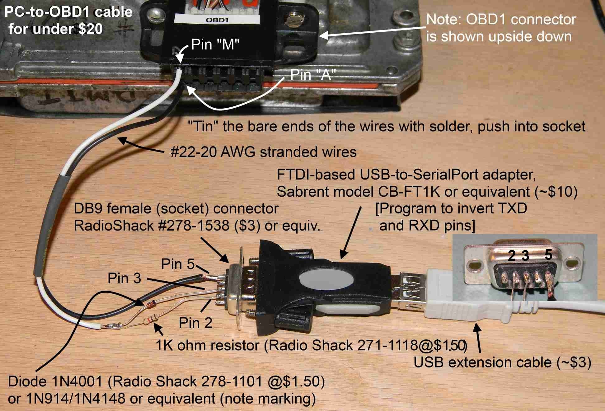
Construct the cable wiring as depicted in the image below. It is advisable to leave the wires slightly longer initially for ease of handling. Ensure proper insulation of the wires and components at the DB9 connector to prevent short circuits. “Tin” the wire ends that will connect to the OBD-1 connector with solder; this will prevent fraying and maintain wire integrity.
Pay close attention to the diode’s polarity. The cathode end of the diode, marked by a black band, must be oriented towards the DB9 connector. The resistor is non-polarized and can be installed in either direction.
Image: A visual representation of the DIY OBD1 cable wiring, clearly showing the placement of the resistor, diode, and wire connections to the DB9 connector.
Step 2: Programming the FTDI Chip
The next crucial step involves reprogramming the FTDI chip within your USB-to-Serial adapter. For this OBD1 cable to function correctly, the Transmit Data (TXD) and Receive Data (RXD) signals need to be inverted.
Download the FTDI configuration utility “FT_Prog” directly from the official FTDI website. Navigate to the “Utilities” section to find the download link.
Image: A screenshot of the FTDI website, specifically highlighting the location for downloading the FT_Prog utility, essential for configuring the USB adapter.
Install and launch FT_Prog on your computer. Connect your USB adapter to a USB port. Press the F5 key within FT_Prog to refresh the device list. Your adapter should appear in the left-hand device list. If multiple devices are listed, disconnect any other USB-to-Serial adapters temporarily. If no devices are detected, double-check the driver installation for your adapter.
Once your device is selected, navigate to “Hardware Specific” and then “Invert RS232 Signals”. Initially, none of the checkboxes should be selected. Activate signal inversion by checking the boxes for both “Invert TXD” and “Invert RXD” as shown in the following image.
Image: A screenshot from the FT_Prog utility showing the “Invert TXD” and “Invert RXD” checkboxes selected, which is the necessary configuration for the OBD1 cable to function.
After configuring the settings to match the image, program the adapter by pressing “Ctrl + P” or by selecting “Devices” then “Program” from the menu. A “Program Devices” window will appear. Click the “Program” button and wait for the “Finished Programming” message to appear at the bottom left of the window.
Image: A screenshot of the FT_Prog “Program Devices” window, prompting the user to click the “Program” button to finalize the configuration changes to the USB adapter.
Close all FT_Prog windows and exit the program. If you ever need to revert the adapter to its original settings, simply repeat these steps but uncheck the “Invert TXD” and “Invert RXD” boxes during the configuration process.
Connecting and Utilizing Your DIY OBD1 Cable
Your DIY OBD1 cable is now complete and ready for use. Connect the appropriate pins to your vehicle’s 12-pin OBD1 connector. Typically, the black wire (ground) connects to pin A, and the white wire (data) connects to pin M on the OBD1 connector of 4th Gen vehicles. Pin assignments may vary depending on the specific vehicle make and model, so always consult your vehicle’s service manual or reliable online resources for accurate OBD1 pinout information.
Connect the DB9 end of your DIY cable to the USB-to-Serial adapter, and then plug the adapter into your computer. Install and launch your chosen OBD1 diagnostic software application. With the correct software and cable connection, you should now be able to communicate with your vehicle’s ECM and perform diagnostic scans.
Important Notes:
- Shorting the wires of this cable will not cause damage but will interrupt communication with the vehicle’s computer while shorted.
- This cable configuration is primarily designed for 4th Gen vehicles and may require modifications (such as adding a resistor and adjusting pin connections) for compatibility with earlier OBD1 systems. Always verify compatibility and pinouts for your specific vehicle.
Building your own 12 pin OBD1 to PC cable offers a practical and economical solution for diagnosing older vehicles. By following these steps and ensuring correct component selection and wiring, you can unlock the diagnostic capabilities of your classic car without the need for expensive, specialized equipment.