Switching from OBD2 to OBD1 engine management in a BMW might seem like a step back, but for performance enthusiasts, it’s a well-trodden path. This guide details the intricacies of an OBD2 to OBD1 conversion, based on a real-world DIY experience, to help you understand if this modification is right for you. We will explore the components involved, the challenges faced, and the potential benefits of choosing OBD1 over OBD2 for your BMW.
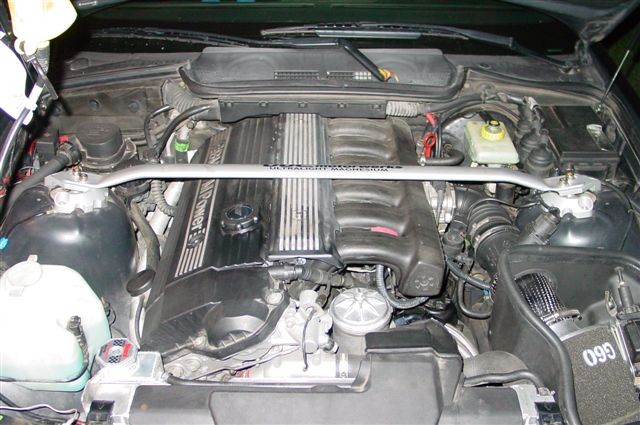
The original OBD2 setup on the S52 engine looked like this:
Alt text: Original OBD2 S52 engine showcasing factory components and wiring before OBD1 conversion, highlighting the complexity of the OBD2 system.
This conversion isn’t just about swapping electronic components; it’s a comprehensive process that requires careful planning and execution. Many might downplay the complexity, but understanding the nuances is crucial for a successful outcome. This guide leverages insights from bimmerforums.com, expert consultations, and countless hours poring over Bentley manual wiring diagrams to provide a thorough walkthrough.
This particular conversion was performed on a 1999 BMW M3, originally equipped with OBD2 engine management and the EWS (Electronic Immobilizer System). The project utilized an OBD1 engine harness from a 1994 325i, along with a ‘red label’ 413 ECU (Engine Control Unit), known for its compatibility with non-EWS systems and popular in performance tuning. An aftermarket performance chip from Active Autowerkes was also incorporated to optimize engine performance after the conversion.
To undertake an OBD2 to OBD1 conversion, you will generally need the following components:
- OBD1 Engine Harness: This is the foundational wiring system designed for the OBD1 engine management.
- OBD1 ECU (413 Red Label): The brain of the OBD1 system, the ECU controls engine functions. The ‘red label’ 413 is favored for its non-EWS compatibility, simplifying installation in some BMW models.
- OBD1 Performance Chip: An optional but highly recommended upgrade to optimize engine performance with the OBD1 ECU.
- OBD1 Intake Manifold: The M50 intake manifold, commonly used in OBD1 conversions, is known for its improved airflow compared to OBD2 manifolds.
- OBD1 Fuel Rail: Designed to work with the OBD1 fuel system configuration, differing significantly from OBD2 setups.
- OBD1 Crank Position Sensor: Essential for engine timing, the OBD1 sensor is different and located in a different position than the OBD2 sensor.
- OBD1 Cam Position Sensor: Another key sensor for engine timing, specific to the OBD1 system.
- OBD1 Knock Sensors (x2): These sensors detect engine knocking and are crucial for engine protection.
- OBD1 Oxygen Sensor: OBD1 systems typically use a single pre-catalytic converter oxygen sensor, unlike the multiple sensors in OBD2 systems.
- OBD1 Hot-Film Air Mass Meter (HFM): Measures the air intake volume, crucial for fuel mixture calculation.
- OBD1 Main Engine Coolant Hose: This hose, connecting to the timing cover, heater core, and radiator expansion tank, differs in OBD1 systems.
- OBD1 Throttle Boot: Connects the throttle body to the intake system, designed for OBD1 components.
- OBD1 Throttle Body (Optional): While the OBD2 throttle body can be adapted, using an OBD1 throttle body simplifies installation.
- OBD1 Valve Cover and Coil Packs (Optional): Choosing between OBD1 or OBD2 valve covers and coil packs involves considering wiring routing and aesthetic preferences.
While conceptually straightforward, the OBD2 to OBD1 conversion involves numerous intricate details. Let’s delve into some key areas that require careful attention.
1. Valve Cover and Coil Packs: OBD2 or OBD1 Choices
The OBD2 valve cover’s design doesn’t accommodate OBD1 coil pack connector routing. OBD2 wiring enters from the passenger side, while OBD1 wiring enters from the driver’s side. This presents a choice:
- Keep OBD2 Valve Cover: Maintain your existing OBD2 valve cover and coil packs. This requires modifying the valve cover, often with a Dremel tool, to allow proper wiring routing for the OBD1 harness.
- Switch to OBD1 Valve Cover: Using an OBD1 valve cover necessitates switching to OBD1 coil packs. Both OBD1 and OBD2 coil versions are compatible with the OBD1 harness, so the choice is largely based on preferred aesthetics and effort.
In this instance, the decision was made to retain the OBD2 valve cover and modify it for wiring clearance.
The OBD2 coil setup appears as follows:
Alt text: OBD2 coil setup illustrating the coil packs and wiring configuration on an OBD2 valve cover, highlighting the passenger-side wiring entry.
And the OBD1 coil configuration is shown below:
Alt text: OBD1 coil setup depicting the coil packs and wiring arrangement on an OBD1 valve cover, emphasizing the driver-side wiring entry point.
2. VANOS Solenoid Wiring: Bridging the Gap
The Variable NockenwellenSteuerung (VANOS) solenoid connector in OBD2 systems has a shorter wire than its OBD1 counterpart. To address this, you have two options:
- OBD1 Solenoid: Replace the OBD2 solenoid with an OBD1 solenoid for direct compatibility with the OBD1 harness.
- Extend OBD2 Wiring: Keep the OBD2 solenoid and extend its wiring to reach the OBD1 harness connector. BMW part # 12-52-2-274-971, a transmission harness originally used for connecting the engine harness to the backup light switch, is perfectly suited for this purpose due to identical connectors.
The BMW transmission harness used for extending the VANOS solenoid wiring is pictured here:
Alt text: BMW transmission harness used as a VANOS solenoid extension, showing the connector type and its application in bridging the wiring length difference between OBD2 and OBD1 systems.
3. Coolant Pipe Configuration: Adapting to OBD1
The main coolant pipe originating from the timing cover differs between OBD1 and OBD2 engines. OBD2 utilizes a metal pipe permanently fixed with sealant, while OBD1 employs a rubber hose connected to an aluminum neck on the timing case cover. Solutions include:
- OBD1 Timing Cover: Replace the OBD2 timing cover with an OBD1 version. This is a more involved solution costing around $100 for the part.
- Coolant Pipe Adapter: Install a coolant pipe adapter (approximately $20) available from BMW performance parts suppliers like Bimmerworld, Active Autowerkes, or Turner Motorsport. This adapter, secured with JB Weld within the OBD2 timing case cover, allows for the use of the OBD1 rubber coolant hose and pipe clamp.
The coolant pipe adapter in situ is visible in this image:
Alt text: Coolant pipe adapter highlighted in an engine bay image, positioned below the oil filter housing, demonstrating its role in adapting the OBD2 timing cover for OBD1 coolant hose compatibility.
4. Intake Manifold: The Performance Advantage of OBD1
The primary performance benefit of an OBD1 conversion often stems from the intake manifold. The M50 intake manifold used in OBD1 systems boasts superior airflow compared to the OBD2 (M52/S52) intake manifolds. This manifold swap is a mandatory part of the conversion. The OBD1 manifold includes an air temperature sensor and a vacuum port for the fuel pressure regulator on its underside, near the firewall. Importantly, the M50 intake manifold directly bolts onto M52/S52 cylinder heads without any modifications.
5. Throttle Body Compatibility: Adapters or OBD1 TB
While you can reuse your OBD2 throttle body, it requires adaptation to properly seal with the OBD1 intake manifold. OBD1 throttle bodies have a flat mating surface designed for a gasket against the OBD1 manifold. OBD2 throttle bodies are inverted, featuring a gasket within the throttle body that seals against a flat surface on the OBD2 manifold. Solutions include:
- Adapter Plate: Install an adapter plate (around $20) between the OBD2 throttle body and OBD1 manifold. This plate provides mating surfaces for both the OBD2 throttle body gasket and the OBD1 manifold.
- Extended Gasket: Use an extended gasket (approximately $15) allowing the OBD2 throttle body to directly seal against the OBD1 intake manifold.
- OBD1 Throttle Body: Using an OBD1 throttle body eliminates the need for adapters or special gaskets, ensuring straightforward compatibility.
6. Coolant Temperature Sender: Adapting Sensor Configurations
OBD2 systems use a single coolant temperature sender located on the cylinder head under intake runner #1. OBD1 systems utilize two senders, positioned under intake runners #1 and #2. To reconcile this difference:
- Splice and Adapt: Splice the OBD1 main engine harness wiring and use the OBD2 plug connector from your original harness to connect to the single OBD2 temperature sender.
- Wiring Adapter: Utilize a plug-and-play coolant temperature sender wiring adapter (around $50) from Turner Motorsport for a cleaner, more integrated solution.
7. Crank Position Sensor: Location and Sensor Swap
The OBD2 crank position sensor is located on the engine block near the starter motor. The OBD1 sensor is positioned on the timing cover, mounted on a circular tab with a 6mm Allen bolt. For the conversion, you must use an OBD1 crank position sensor. The OBD2 sensor can be left in place to plug the hole in the engine block.
8. Fuel Lines and Fuel Pressure Regulator: Major System Differences
Significant differences exist in the fuel delivery systems between OBD2 and OBD1. OBD2 fuel rails have both fuel lines connecting at the rear, near the firewall, and the fuel pressure regulator is located externally, forward of the fuel filter under the car. OBD1 fuel rails have the supply line at the front and the return line at the rear, with the fuel pressure regulator integrated directly onto the fuel rail.
Therefore, using the OBD1 fuel rail is mandatory for this conversion. This necessitates modifications to the fuel lines. The OBD2 fuel pressure regulator must be removed from under the car. New 8mm fuel lines need to be routed to the OBD1 fuel rail. Bridge the gap left by the removed OBD2 fuel pressure regulator using new fuel line, connecting the feed from the fuel filter to the front of the OBD1 fuel rail and the return line from the rear of the OBD1 fuel rail to the existing return line under the car. Finally, connect the OBD1 fuel pressure regulator vacuum line to the one-way valve located on the underside of the OBD1 intake manifold, at the rear corner closest to the firewall.
9. Positive Crankcase Ventilation (PCV): Adapting Venting Systems
The OBD2 crankcase ventilation system differs from OBD1. Several approaches exist:
- OBD2 Valve Cover & PCV: If retaining the OBD2 valve cover, keep the OBD2 PCV setup. Devise a method to mount the breather valve (cone-shaped plastic valve) under the intake manifold.
- OBD1 Valve Cover & PCV: If using an OBD1 valve cover, use the OBD1 breather valve, which clips onto the crankcase vent port. This valve connects via a vacuum line to the ICV-to-intake manifold plug and a larger oil drain line to the dipstick.
- Breather Catch Can: Connect a hose to the crankcase vent and route it to a breather catch can system.
In this conversion, a hybrid approach was used:
Alt text: Hybrid PCV setup utilizing components from both OBD1 and OBD2 systems, showcasing the connection of the OBD2 valve cover to the OBD1 breather valve via a rubber hose and barbed connector for oil drain to the dipstick.
A short length of 1″ rubber hose was used to connect the OBD2 valve cover to the OBD1 breather valve, with a barbed connector joining the oil drain line to the dipstick.
10. Idle Control Valve (ICV): Reusing OBD2 Components
The Idle Control Valves (ICVs) are identical between OBD1 and OBD2 systems. You can reuse your OBD2 ICV. You will need to acquire the correct connector and hoses for the ICV-to-intake manifold connection and the hose connecting the ICV to the throttle boot vacuum port, ensuring proper fitment within the OBD1 configuration.
11. Fuel Tank Breather Valve: Vacuum Line Adaptation
The OBD2 fuel tank breather valve can be reused. Adaptation involves acquiring fittings to connect the vacuum hose to the vacuum port on the throttle boot. Standard hardware store fittings (3/8” and 5/8” barb fittings) can be used to create a rigged connection to the throttle body vacuum port.
12. Oxygen Sensors and Secondary Air Pump: Emission System Simplification
OBD2 systems incorporate a secondary air pump for emissions control, which is completely eliminated in an OBD1 conversion. Furthermore, OBD2 systems use four oxygen sensors (two pre-catalytic converter and two post-catalytic converter), while OBD1 management uses only a single pre-catalytic converter oxygen sensor. The ports for the removed OBD2 sensors in the exhaust headers and catalytic converter need to be plugged. M18 bolts, readily available at auto parts stores (Toyota Land Cruiser oil pan drain bolts are M18), can serve as plugs.
13. Oil Pan & Dipstick: Misconceptions Debunked
Contrary to some beliefs, an OBD1 oil pan and dipstick are not required for this conversion. The OBD2 oil pan and dipstick are fully compatible and can be used without any issues or modifications.
14. EWS (Electronic Immobilizer System): Bypassing Security
The presence of EWS varies across E36 models. While the ECU used in this conversion was from a non-EWS vehicle, ignition issues can still arise post-conversion. A simple modification to the main engine harness addresses potential EWS conflicts. Locate wire #66 at the ECU connector (solid green or black/violet according to Bentley diagrams), remove the protective rubber boot from the connector, cut wire #66, and insulate both ends with electrical tape. This bypasses any residual EWS interference.
15. Power Distribution & Grounding: Careful Reconnection
Proper power distribution and grounding are critical. Always disconnect the negative battery terminal before working on electrical systems. Document the original OBD2 power and ground connections with photos or labels before disassembly. The OBD2 main battery positive post is located on the passenger side near the ECU compartment. The OBD2 distribution box, mounted parallel to the fender, will need to be slightly relocated to reach the OBD1 harness power connections. Removing the secondary air pump reveals screw holes that allow for repositioning the distribution box closer to the firewall. Ensure a secure and tight fit.
Alt text: Relocated power terminal in the engine bay, showing the distribution box repositioned closer to the firewall after OBD2 to OBD1 conversion, with the original mounting bracket visible on the left.
Identify power feeds (RED wires) and grounds (BROWN or BLACK wires) carefully. Double-check by peeling back wiring sheaths if unsure. Connect the main power feed to the OBD1 harness. A ground connection will be located under the OBD diagnostics port. There are also large power feeds to the starter and smaller feeds to the fuse box. Another ground wire (small, with a round terminal connector) from the spark plug rail needs to be grounded to the bolt securing the engine hoist loop on the VANOS unit.
16. General Wiring: Labeling is Key to Success
Meticulous labeling of connectors before disconnecting the OBD2 harness is paramount. Utilize Bentley wiring schematics to identify each connector on the OBD1 harness. Label each connector with painter’s tape and a marker, clearly indicating its intended component. The engine bay quickly becomes a tangle of wires, making unlabeled connectors indistinguishable. While wire lengths are generally practical, clear labeling prevents confusion and ensures correct connections. Photographing power and ground connections during OBD2 harness disassembly is also highly recommended, especially the starter wiring, as its four wires can easily be misconnected.
Alt text: Labeled OBD1 engine harness prepared for installation, showcasing the use of painter’s tape and markers to identify each connector for simplified and accurate wiring during the OBD2 to OBD1 conversion process.
Final OBD1 S52 Configuration and Performance
This DIY OBD2 to OBD1 conversion on a 1999 M3 S52 engine involved a comprehensive parts list and careful execution. The final configuration included:
- 1999 M3 OBD1 S52
- Active Autowerkes (AA) Cam Chip
- Sunbelt Cams
- Euro 3.5″ HFM
- Conforti 3.5″ Intake
- 24lb Injectors
- Sunbelt Valve Springs
- ARP Headstuds
- AA Race Headers
- AA Race Exhaust
- Zionsville Competition Radiator
- Euro Oil Cooler
The completed OBD1 S52 engine after conversion looked like this:
Alt text: Final OBD1 S52 engine setup after successful conversion, displaying the cleaner OBD1 engine management system and performance upgrades, contrasting with the original OBD2 configuration.
Dyno testing after the conversion yielded initial results of 253 rear-wheel horsepower (RWHP) and 228 lb-ft of torque. After software revisions to lean out a rich fuel mixture, subsequent dyno runs achieved 262 RWHP and 230 lb-ft of torque, with optimized Air-Fuel Ratio (AFR).
Conclusion: OBD2 to OBD1 – A Worthwhile Conversion?
Converting from OBD2 to OBD1 engine management is a significant undertaking, far beyond a simple ‘electronics swap.’ It requires meticulous attention to detail, a thorough understanding of engine systems, and careful execution. However, for BMW performance enthusiasts seeking to maximize the potential of their S52 engines, particularly for applications where simplified engine management and specific tuning advantages are desired, the OBD1 conversion remains a viable and rewarding modification. The improved airflow from the M50 intake manifold and the tuning flexibility of the OBD1 ECU can contribute to noticeable performance gains. If you are considering an OBD2 to OBD1 conversion, thorough research, careful planning, and patient execution are key to a successful outcome.